0
$\begingroup$

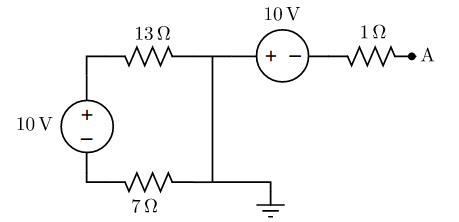
I am trying to calculate the voltage in A, in the following circuit:

enter image description here

That means I have to calculate the voltage at the ground end relative to A, or with other words: "go from ground to A and add or substract each voltage".

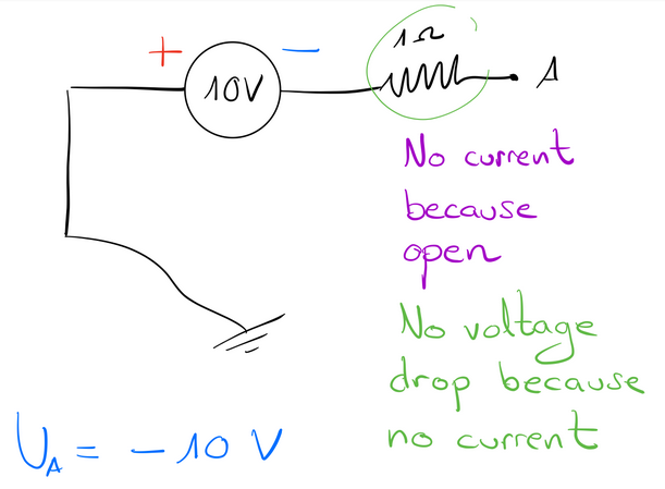
If the loop wasn't there, this is what I can say about $U_A$.

enter image description here

But there is my first confusion, since ground systems are made to close the circuit, and I don't know if that allows a current to actually flow between A and ground.

Or maybe I can consider the space bewteen A and ground like a huge resistance, so there really is no current going on there.

But even assuming that is correct, I don't know how to proceed with the loop, because:

  • There will be current in the loop.
  • Voltage in the loop must sum zero.
  • Each resistance has a different value, so they will have a different voltage drop.
  • I don't know how to calculate the current in the loop, so I don't know how to calculate the voltage in each resistance, and hence... I don't know if there is any voltage in the middle connection (which will affect $U_A$).

A teacher said that the cable with nothing in it, behaves like a shortcircuit, so I can just imagine it's not there. That would be very clear if there wasn't a voltage source in the loop.

But the fact that there is a voltage source in the loop makes it hard to believe that there won't be any current and voltage on that side of the circuit.

How exactly does the voltage source on the left side affect the cable that has nothing in it?

UPDATE

Thanks to uriyaba's and Ofek's answers I now understand that there is no voltage difference in the middle connection.

But Ofek's answer, even though it's very clear, is somehow "jumping over" the confusion. It calculates the current in the loop by assuming that there is no voltage in the center connection, so it is not actually mathematically justifying the fact that there is no voltage there, it's just assuming it.

If we apply Kirchhoff's second law in the loop, it would be an equation with two unknown parameters:

$10V − 13Ω⋅I −7Ω⋅I - x V = 0$

Where $x V$ is the unknown amount in the branch.

So this is not the way to go yet, to know what the value for x is.

There is something else that must come into the game.

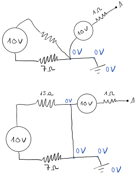
I tried to expand on uriyaba's answer and made this drawing:

enter image description here

But the 0 V confuse me.

If there really where 0 V in that branch, the loop would not have any current because charge carriers wouldn't have any "reason" or "motivation" to cross that connection.

Of course, what is confusing me, is the representation of the circuit.

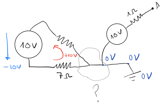
Maybe this makes it clearer, but I am still not getting what really goes on in that central area:

enter image description here

How can I have "yes voltage difference" and "no voltage difference" at the same spot?

What would a connection like this look like in reality?

If the loop was independent and not connected to anything, I wouldn't have any doubt. Any cable connecting the two resistors wouldn't have a voltage drop (ideally of course).

But the case is, it's in fact connected to another voltage source.

$\endgroup$
4
  • 2
    $\begingroup$ Alvaro, have you tried adding a resistor of resistance $R$ from $A$ to ground, solving for the voltage across it in terms of $R$, and then taking the limit as $R\rightarrow\infty$? Note: the ground symbol here only means (in this case) that this is the zero volt reference node, i.e., imagine placing the black lead of your voltmeter there and leaving it. $\endgroup$ Commented Dec 25, 2019 at 11:58
  • $\begingroup$ @AlfredCentauri This is a very good approach. It helps me get that the answer is $U_A = -10 V$. But still, I wonder what happens in the loop. A teacher said that the cable with nothing in it, acts as a shortcircuit, so I can just imagine it's not there. That would be very clear if there wasn't a voltage source in the loop. But the fact that there is a voltage source in the loop makes it hard to believe that there won't be any current and voltage on that side of the circuit. $\endgroup$ Commented Dec 25, 2019 at 14:30
  • $\begingroup$ There will be current in the loop, but it won't leak out of it. The voltage difference between the "left side" of the resistors is $10V$ but the voltage difference between the "right side" will be $0$, meaning it will behave like a short circuit for your problem $\endgroup$ Commented Dec 25, 2019 at 17:37
  • $\begingroup$ @OfekGillon Thanks for your kind answer. I cannot understand the fact that the voltage difference between the "right side" will be 0. Would that be true if there was only the loop without the right part of the circuit? I would highly appreciate it if you describe what is going on in that loop. $\endgroup$ Commented Dec 25, 2019 at 17:47

2 Answers 2

1
$\begingroup$

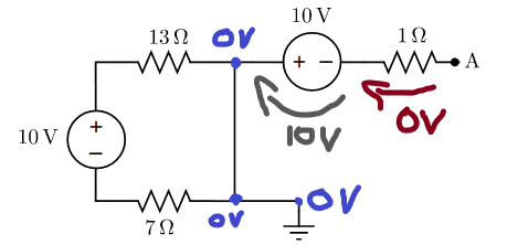
The potential on the blue points I drew on the circuit is $0V$, since they are all shorted and connected to the ground. Because of this, the leftmost voltage source practically doesn't affect the voltage you want to calculate.

Like you said, the voltage along the gray line is $10V$, and the voltage along the red arrow is $0V$.

So in total, the voltage from the ground to point $A$, is equal to $0-10-0=-10V$.

Remember - No current means no voltage, but there can be voltage between to points without current flowing between them!

enter image description here

$\endgroup$
5
  • $\begingroup$ Wonderful answer. But I still do not understand the $0 V$. Starting from the ground, that's by definition of ground the $0 V$ reference. The next node is also $0 V$ because it's directly connected to the ground. But the upper $0 V$ you drew is not clear to me. There is a voltage source connected in parallel which does force a voltage difference between those points. (Of course I do not intent to say you are wrong. You are definitely right, it's me. I am too ignorant to see this) $\endgroup$ Commented Dec 25, 2019 at 18:17
  • $\begingroup$ Thanks a lot. I selected Ofek's answer because it is more complete, but you are the inspiration. $\endgroup$ Commented Dec 25, 2019 at 18:53
  • $\begingroup$ Thanks for the input! I think I know why you're confused; You would be right saying that the voltage between the upper 0V nodes is equal to 10V if the voltage source was connected in parallel to the branch, with no resistors. There's voltage on both the resistors on the leftmost branch! $\endgroup$
    – uriyabsc
    Commented Dec 25, 2019 at 18:54
  • $\begingroup$ That clarifies it even more. I guess the same is true with only one resistor then. $\endgroup$ Commented Dec 25, 2019 at 18:55
  • $\begingroup$ Exactly! I'm glad I've been helpful :) $\endgroup$
    – uriyabsc
    Commented Dec 25, 2019 at 18:58
1
$\begingroup$

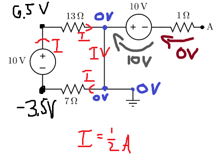
I see your confusion so I took uriyaba's wonderful drawing and added details that maybe will make it more clear:

enter image description here

$\endgroup$
10
  • $\begingroup$ For each resistor you drew a voltage of half it's resistance value because I = 0,5 A. Could you please explain where those values come from? Those number make it be this way but why is it not I = 0,2 and then there is some voltage in the blank cable too? Thanks a lot for taking your time. $\endgroup$ Commented Dec 25, 2019 at 18:45
  • 1
    $\begingroup$ I just applied Kirchhoff's law for the right circuit and got that the current needs to be half an ampere. So by defining the down-right corner to be "0 volts" I just continued using Ohm's law to figure out the voltage in each place in the circuit. $\endgroup$ Commented Dec 25, 2019 at 18:47
  • $\begingroup$ How does the Kirchhoff's law result in I being half an Ampere? (Sorry I am not making fun or anything, I really don't see it) I know Kirchhoff's law 1 and 2 but I do not see them applying here and resulting in half an Ampere current. $\endgroup$ Commented Dec 25, 2019 at 18:49
  • 2
    $\begingroup$ The voltage across the loop will be $$10V - 13\Omega \cdot I - 7 \Omega \cdot I = 0 \Rightarrow 10 V = 20 \Omega \cdot I $$ $$ I = \frac{10 V}{20\Omega} = 0.5 \frac{V}{\Omega} = 0.5 A$$ $\endgroup$ Commented Dec 25, 2019 at 18:50
  • $\begingroup$ I used the fact that the current is the same everywhere using the current law (in every node the current doesn't go elsewhere) $\endgroup$ Commented Dec 25, 2019 at 18:51

Not the answer you're looking for? Browse other questions tagged or ask your own question.