I am aware that at resonance, the voltage across the inductor and the capacitor are equal in magnitude and opposite in phase. However, I want to know how the voltage across $L$ and $C$ vary if I vary the frequency on either side of the resonant frequency and if any relationship exists between the two (e.g. whether one decreases while the other increases with frequency below the resonant frequency and swaps their behaviour above the resonant frequenc).
Update: For and LCR circuit, we can write the following expressions for the voltages across the capacitor $V_c$ and the inductor $V_L$:
$V_c=\frac{-j}{\omega C}\frac{V}{R+j(\omega L - \frac{1}{\omega C})}$
and
$V_L=V\frac{ j\omega L }{R+j(\omega L - \frac{1}{\omega C})}$
($V$ is the rms volatge applied to the circuit and $j=\sqrt{-1}$)
And, the magnitudes of of $V_c$ and $V_L$ are:
$|{V_c}|=\frac{V}{\omega C\sqrt{R^2+(\omega L - \frac{1}{\omega C})^2}}$
and
$|V_L|=\frac{V \omega L}{\sqrt{R^2+(\omega L - \frac{1}{\omega C})^2}}$
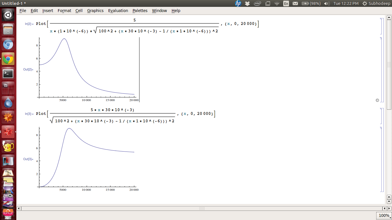
And I plotted $|V_c|$ and $|V_L|$ as functions of $\omega$ using Mathematica and here are the results:
The first plot shows the variation of $|V_c|$ with $\omega$ and the second plot shows the variation of $|V_L|$ with $\omega$. The voltages are along the $Y axis$ and $\omega$ is along the $X axis$.
(I used some standard values: $V=5\,\text{V}$, $R=100\,\Omega$, $C=1\,\mu\text{F}$ and $L=30\,\text{mH}$.)

