4
$\begingroup$

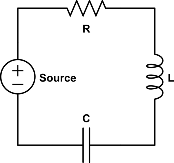
Consider an RLC circuit in series, of the form

If the source drives the circuit in AC at the resonance frequency $\omega =1/\sqrt{LC}$, the peak-to-peak voltages on the capacitor and the inductor, $$ V_C=\left|\frac{Z_C}{Z_\mathrm{tot}}\right|V_S=\frac{\frac{1}{\omega C}}{\sqrt{R^2+\left(\omega L-\frac{1}{\omega C}\right)^2}}V_S \quad \text{and}\quad V_L=\left|\frac{Z_L}{Z_\mathrm{tot}}\right|V_S=\frac{\omega L}{\sqrt{R^2+\left(\omega L-\frac{1}{\omega C}\right)^2}}V_S ,$$ can both be larger than the peak-to-peak voltage $V_S$ of the source.

The math might say one thing, but this is till terribly counterintuitive. How can this be?

$\endgroup$
5
  • $\begingroup$ The sum of $V_C$ and $V_L$ can be greater than the supply voltage because the voltages are out of phase and don't simply add together. If you're claiming the voltages are individually larger than the supply voltage I think we'd need to see a circuit diagram showing an example. $\endgroup$ Commented Dec 8, 2015 at 7:58
  • $\begingroup$ I'm sorry i missed the word RESONANCE. At resonance aren't Vl is equal to Vc so don't they cancel each other? $\endgroup$
    – Emma
    Commented Dec 8, 2015 at 8:08
  • $\begingroup$ Hi Emma, I've taken the liberty to beef up your post with some backing to answer @JohnRennie's concerns, trying to keep to your original intent. If I have misinterpreted it please feel free to rollback the changes or clarify what you mean to ask. $\endgroup$ Commented Dec 8, 2015 at 12:11
  • $\begingroup$ Closely related by the OP: Parallel RLC circuit , how branching currents may each be larger than source current at resonance? $\endgroup$ Commented Dec 8, 2015 at 12:13
  • $\begingroup$ @Emma, did the answer and comments make this issue more intuitive? $\endgroup$ Commented Feb 12, 2021 at 19:29

2 Answers 2

1
$\begingroup$

The given RLC circuit with an external voltage $V_S(t)$ is described by the following differential equation: $$V_S(t) = LI(t) + RI(t) + \frac{1}{C}Q(t)$$ or using $I(t)=\dot{Q}(t)$ $$V_S(t) = L\ddot{Q}(t) + R\dot{Q}(t) + \frac{1}{C}Q(t).$$

This is very similar to the mechanical oscillator
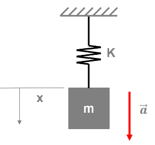
mechanical oscillator

which is described by the differential equation $$F_S(t) = m\ddot{x}(t) + \gamma\dot{x}(t) + kx(t).$$ where $F_S(t)$ is an external force, $-\gamma\dot{x}(t)$ is the frictional force, and $-kx(t)$ is the spring force.

Comparing both differential equations we get the following analogies between electrics and mechanics:

$$\begin{array}{|cc|cc|} \bf{\text{electric}} & & \bf{\text{mechanical}} & \\ \hline \text{voltage} & V(t) & \text{force} & F(t) \\ \hline \text{current} & I(t) & \text{velocity} & \dot{x}(t) \\ \hline \text{charge} & Q(t) & \text{position} & x(t) \\ \hline \text{inductance} & L & \text{mass} & m \\ \hline \text{resistance} & R & \text{friction constant} & \gamma \\ \hline \text{reciprocal capacitance} & 1/C & \text{spring constant} & k \\ \hline \end{array}$$

We all have an intuitive knowledge about the behavior of this mechanical oscillator.

When we apply an external force $F_S(t)=\hat{F}_S\sin(\omega t)$ with a frequency $\omega$ equal to the resonance frequency $\omega_0=\sqrt{\frac{k}{m}}$, then the inertial force $m\ddot{x}(t)$ and the spring force $-kx(t)$ cancel each other. Therefore the external force $F_S(t)$ only needs to compensate for the small frictional force $-\gamma\dot{x}(t)$. Because of this, both the inertial force and the spring force can have much larger amplitudes than the small external force.

Taking the analogies from the table above you can apply the same intuition to the electric RLC circuit.
$\endgroup$
0
$\begingroup$

Well, here I take into consideration that you have an elementary idea of phasors. In DC circuits with resistors, you sum up the voltage drops, which equals the source voltage. But here, since we are dealing with AC, we have to consider the vector sum of the R, L and C voltages. This will definitely equal the source voltage, if done correctly. I am telling you what to do. You compute the potential drops along R, L and C. Let $V_1$, $V_2$ and $V_3$ be the P.D across R, L and C respectively. First, you draw the XY plane on a paper. Then, draw a vector representing $V_1$ along the X axis. As P.D across inductor leads the current by 90 degrees, you draw $V_2$ along positive Y axis and $V_3$ along the negative Y axis (Capacitor voltage lags behind the current by $\pi/2$). Then compute the resultant of the 3 vectors, the magnitude of which will be equal to $V_0$ (source voltage). You can also compute the phase difference by which the source voltage leads or lags behind the current. There is absolutely no problem if $V_1$ or $V_3>V_0$. It's the resultant of $V_1$, $V_2$ and $V_3$ that we have to consider (since they are sinusoidally varying alternating quantities). You will get the same result if you frame a differential equation and solve it, but phasors simplify our calculations to a great extent.

$\endgroup$
1
  • $\begingroup$ While this gives some idea of how to calculate the response, it gives no insight in to why you get that response. $\endgroup$
    – Jon Custer
    Commented Dec 8, 2015 at 15:27

Your Answer

By clicking “Post Your Answer”, you agree to our terms of service and acknowledge you have read our privacy policy.

Not the answer you're looking for? Browse other questions tagged or ask your own question.