1
$\begingroup$

I am trying to understand the relationship between the diffraction pattern produced when shining light onto a 2D lattice and the reciprocal lattice of the direct lattice in question.

So suppose we have a 2D square lattice with lattice parameter $a$. All points in this lattice can be represented by a vector of the form $D_{n_x,n_y}= n_xa\hat{x}+n_ya\hat{y}$ where $n_x,n_y\in Z$. The reciprocal lattice of this direct lattice can then be represented by all points of the form $R_{n_x,n_y}= k_x\frac{2\pi}{a}\hat{x}+k_y\frac{2\pi}{a}\hat{y}$ where $k_x,k_y\in Z$. Now my question is: how is this reciprocal lattice related to the diffraction pattern produced when I shine a monochromatic plane wave with wavelength $\lambda \approx a$ onto the 2D square lattice from the perpendicular $\hat{z}$ direction? The webpage https://www.doitpoms.ac.uk/tlplib/diffraction/diffraction3.php indicates that they are analogous (as seen in the screenshot from the webpage in question below ) but I have some issues with this.

For starters, the diffraction pattern must surely depend on the incident wavelength $\lambda$, but the reciprocal lattice does not depend on the wavelength at all. So does the incident wavelength simply scale the reciprocal lattice so that it equals the diffraction pattern? Secondly, how are the amplitudes of the diffraction pattern peak points determined? My thinking is that they must be proportional to the square of the corresponding fourier components of the periodic electron density in the unit cell.

Finally, and perhaps most importantly, if we change the direction of the incoming light so that it is no longer perpendicular to the 2D lattice but at an angle to the perpendicular, we clearly change the diffraction pattern but we still do nothing to the reciprocal lattice. For example, if the incident beam is positioned so that it is parallel to the surface of the flat 2d square sheet, then I expect the diffraction pattern to look something like that of a 1D diffraction grating and not like a 2d square reciprocal lattice. So what is the exact relationship between the diffraction pattern of a 2D lattice and the reciprocal lattice of the 2D lattice in question? The same question can apply to 3D lattices as well however the 2D case alone should suffice. Any help on this issue would be greatly appreciated!

$\endgroup$
2
  • $\begingroup$ Try Ashcroft Mermin Chapter 1. It will clear all your doubts. $\endgroup$ Commented Jun 7 at 10:15
  • $\begingroup$ @SchrodingersCat Ashcroft and Mermin chapter 1 deals with the Drude theory of metals. I assume you are referring to chapters 4 through 6 of the same book, which deal with diffraction and the reciprocal lattice?Unfortunately these do not touch on the diffraction pattern arising from a beam of x rays perpendicularly incident on a 2D lattice. They only deal with 3d lattices and x rays incident on 2d crystals parallel to the 2d plane. $\endgroup$ Commented Jun 7 at 18:29

2 Answers 2

2
+50
$\begingroup$

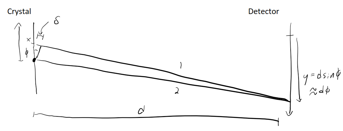
The relationship between lattices and reciprocal lattices can be derived in the Fraunhofer approximation, which says that the deflection of the light rays leaving the solid and hitting the detector is small. Your question can be answered in 1D, so let's work through that case for simplicity. In the picture below, this means that $d \gg x, y$. It also implies that the two rays labeled 1 and 2 are of approximately equal length, but differ by some small amount $\delta \approx \phi x \approx x y / d$. The amplitude of a light ray emitted from a point $x$ in the object and propagating along one of these rays to the detector is then

$$e^{2\pi i (d+\delta) / \lambda} \propto e^{2\pi i x y / \lambda d}$$

Adding up the fields from every point in the object gives the field at the detector

$$\int_{-\infty}^\infty f(x) e^{2\pi i x y / \lambda d} dx = \tilde{f}(y / \lambda d)$$

where $f(x)$ is the scattering amplitude of the object at position $x$ and $\tilde{f}(k)$ is the Fourier transform of $f(x)$. This derives the connection between diffraction patterns and reciprocal lattices.

The probability to detect a photon at position $y$ is given by the magnitude squared of the above. As you can see, the diffraction pattern gets scaled by $\lambda d$, so it does indeed depend on the wavelength, as you guessed.

Fraunhofer diffraction

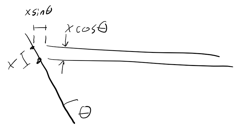
Finally, what about tilting the object by an angle $\theta$? This has two effects. One is that it changes the relative distance $\delta$ from the object to the screen by a distance $x \sin(\theta)$. However it also changes how far the incident light must travel before hitting the object, so the net effect on the phase of the light hitting the detector is unaffected by this tilt.

The second effect is, as you mention, that the projection of the object along the propagation direction of the light. This effectively contracts the size of the object according to the transformation $x \rightarrow 1 / \cos \theta$. Plugging this into the first equation, you can see that this has the effect of expanding the diffraction pattern by a factor $1/\cos\theta$.

Tilted object case

$\endgroup$
5
  • $\begingroup$ Thanks for the great response. Just two issues I need to clear up. The first is simple: For the case of a 2d square lattice, the f(x) in your integral would become $f(x,y)$ where $f(x,y)$ is the convolution of a 2d square dirac comb and a electron density function $\rho(x,y)$ for the unit cell right? So that $ \tilde{f}(y / \lambda d,x/\lambda d)$ would be the product of the reciprocal lattice and $\tilde{\rho}(x,y)$ ? Secondly, I can see how the change in distance from object to the screen, $x\sin(\theta)$, is cancelled out by the equal and opposite change in the distance from the ... $\endgroup$ Commented Jun 2 at 10:24
  • $\begingroup$ ... incident ray to the object. I can also see how the size of the object is effectively contracted by $x\cos(\theta)$. What do we do with this $x\cos(\theta)$ though? Do we use $f(x\cos(\theta))$ in the integral as well as substitute $d(x\cos(\theta))$ for $dx$ and sub $x\cos(\theta)$ for $x$ in the complex exponential as well? I can't see how this would result in an expansion of the pattern by $1/\cos(\theta)$ . $\endgroup$ Commented Jun 2 at 10:26
  • 1
    $\begingroup$ Yes the generalization to 2D is as you say. My scaling transformation was wrong at first. $f(x) \rightarrow (f(x/\cos \theta)$ compresses the pattern. Then do a few change-of-variables until you get the $\cos \theta$ on the right-hand side with $y$. Or better yet, look up the relevant Fourier transform identities to be sure. Contraction in real-space expands in Fourier space, because contractions increases spatial frequencies. $\endgroup$
    – user34722
    Commented Jun 3 at 1:22
  • $\begingroup$ Okay I think I understand most of it now. To summarize: the diffraction pattern produced on a screen by shining monochromatic light onto a 2D lattice is in fact the Fourier transform of the projection of the 2d lattice onto the screen and not the transform of the actual lattice. When the incident light is perpendicular to the lattice, then the projection is simply equal to the lattice. But when the lattice is rotated, the projection compresses and hence by the Fourier Scale Theorem, the diffraction pattern expands? $\endgroup$ Commented Jun 3 at 6:42
  • 1
    $\begingroup$ That's correct! $\endgroup$
    – user34722
    Commented Jun 3 at 6:48
1
$\begingroup$

To deal with the problem you can use the formulation of von Laue for diffraction. This is valid in the kinematics approximation where waves are poorly absorbed by the lattice and the refractive index is close to 1.

For simplicity is easy to consider a structure with one atom per unit cell (in this case the scattering centre are point-like object):

  • the radiation is elastically scattered by the individual atoms;
  • the scattered waves are spherical.

In this situation the Von Laue condition is valid: $$ \mathbf k_f = \mathbf k_i + \mathbf g $$ $\mathbf k_i$ is the wave-vector of the incoming radiation, $\mathbf k_f$ is the wave-vector of the diffracted radiation and $\mathbf g$ is a generic vector of the reciprocal lattice.

Even though the lattice is 2D the problem has to be considered in 3D. So the reciprocal lattice will be composed by straight lines perpendicular to the lattice plane and passing trough the point of the 2D reciprocal lattice (the yellow lines in the image below).

To clarify this idea we can consider the real points in the 3rd dimension as infinitely spaced, so the reciprocal points in the 3rd dimension are infinitely close.

Because the scattering considered is elastic we also have to take in account that: $$ |\mathbf k_i|^2= |\mathbf k_f|^2$$

This considerations give rise to the Ewald construction: given a certain incoming radiation characterized by $\mathbf k_i$ we can create a sphere with radius $|\mathbf k_i|$, and center in the tail of $\mathbf k_i$. The reciprocal lattice needs to be placed with one of his point coincident with the head of $\mathbf k_i$.

$\mathbf k_f$ are all the possible vector with tail in the center of the sphere and head in a point that is both a surface point of the sphere (so $ |\mathbf k_i|= |\mathbf k_f|$) and a point of the reciprocal space. Ewald sphere for a 2D lattice

Extending the direction of $\mathbf k_f$ from the sample to a screen we obtain a diffraction point. The screen considered can be a plane or a generic surface (in LEED a spherical screen is used).

This construction is really general, is valid for transmitting grating or reflecting grating, and we can consider all the inclination between the grating and the incoming ray.

For the limit case of the rays parallel to the lattice is important to specify how the third dimension of the lattice is made.

$\endgroup$

Your Answer

By clicking “Post Your Answer”, you agree to our terms of service and acknowledge you have read our privacy policy.

Not the answer you're looking for? Browse other questions tagged or ask your own question.