6
$\begingroup$

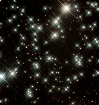
Very often when viewing pictures of the cosmos taken by telescopes, one can observe that larger/brighter stars do not appear precisely as points/circles on the image. Indeed, the brighter the light from star, the more we see this effect of four perpendicular rays "shooting" out from the star.

Stars1

(Taken from this page.)

My question is: what are the optics responsible for this effect? I would suppose that both the hazy glow around the stars and the rays shooting outwards are optical effects created by the camera/imaging device, but really can't surmise any more than that. (The fact that the rays are all aligned supports this, for one.) A proper justification, in terms of (geometrical?) optics for both the glow and the rays would be much appreciated.

Here are a few other examples of such images:

$\endgroup$

4 Answers 4

15
$\begingroup$

This is, as Lubos mentioned, an effect of the wave nature of light, and cannot be explained using geometrical optics.

What you are seeing is called the Point Spread Function (PSF) of the imaging system. Because stars are so far away that they are effectively point sources of light (i.e. they are spatially coherent) their image will be the PSF of the imaging system. Up to a scale factor, the PSF is the Fourier transform of the pupil of the imaging system. For a lens system, the pupil is usually just a circle, so the PSF is the 2D Fourier transform of a circle:

$$ \frac{J_1(2 \pi \rho)} {2 \pi \rho} $$

Where $J_1$ is the order 1 bessel function of the first kind.

However, most modern telescopes are built with reflective optics, and there are various obscurations in the pupil due to the structures that support the secondary mirror. This more complicated pupil shape can produce a variety of artifacts in the PSF. The starburst pattern in your example images could be due to a simple "plus" shaped structure supporting the secondary mirror, but the effect is so strong that I suspect it was emphasized for creative effect. I'm not sure how the Hubble PSF looks, off the top of my head.

In general, an image can be represented by the convolution of the ideal image $g(x,y)$ with the PSF, usually denoted $h(x,y)$. In the case of a point source (so $g(x,y)$ is a delta function, $\delta(x,y)$) it is trivial that the image is a copy of the PSF:

$$h(x,y)=\int_{-\infty}^{\infty} \delta(\xi,\eta) h(x-\xi, y-\eta) d\xi d\eta $$

But in the case of a more complicated object, the convolution by the PSF acts to smooth or blur the image. This is why an out of focus camera produces blurry images. Although aberrations also degrade the image under a geometrical approximation, this is more accurate. The geometrical case and the wave optics (diffraction) result will become closer as the aberrations become large.

Sometimes this effect is produced intentionally. You can actually buy filters for commercial cameras that have a fine grid of wires to produce this starburst effect for creative purposes.

NB: This answer ignores any discussion of phase effects in diffraction (because I'm short on time, I may update later). If you would like to learn about diffraction and the wave optics approach to imaging, the leading text on the planet is "Introduction to Fourier Optics" by J. Goodman. It is an absolutely spectacular book.
$\endgroup$
8
  • $\begingroup$ @Colin: Thanks for your detailed answer. I'll have a closer look at it shortly! :) $\endgroup$
    – Noldorin
    Commented Jan 19, 2011 at 18:24
  • $\begingroup$ @Noldorin: Of course:) I do plan on adding a little bit to it though. There is a lot of interesting details that I completely ignored. It will have to wait until I get home from work though. $\endgroup$
    – Colin K
    Commented Jan 19, 2011 at 18:27
  • $\begingroup$ Sounds great; I look forward to it. It would be interesting to simulate these optical effects computationally in fact (perhaps as an image processor), which I may well do. $\endgroup$
    – Noldorin
    Commented Jan 19, 2011 at 18:30
  • 1
    $\begingroup$ @Noldorin: You're talking about things very close to what I do professionally! I will be expanding this answer, but if you have other questions on this or related topics, please ask. I'd be happy for the chance to get some more good answers on here:) $\endgroup$
    – Colin K
    Commented Jan 19, 2011 at 18:39
  • $\begingroup$ @Colin K: Yes, I just noticed - you're studying/working as an optical engineer! :) Thanks for the openness. I'm definitely interested in these sorts of topics. (I've been doing some light research on methods and solutions to the rendering equation recently - photon mapping, ray tracing, etc. Interesting stuff.) $\endgroup$
    – Noldorin
    Commented Jan 19, 2011 at 19:13
3
$\begingroup$

a great question. These crosses around the stars are called "diffraction spikes". They emerge because of wave properties of light - interference around rods that have to be inserted into the reflective telescope. See e.g.

http://en.wikipedia.org/wiki/Diffraction_spike

http://apod.nasa.gov/apod/ap010415.html

All the best Lubos

$\endgroup$
2
  • $\begingroup$ Many thanks. I suspected they may not be geometrical, but was not sure. Now that I have the pointers, the physics should be easy to understand. :) $\endgroup$
    – Noldorin
    Commented Jan 19, 2011 at 18:23
  • $\begingroup$ That is one reason why planetary astronomers prefer Cassegrain reflectors (where a glass corrector plate holds the secondary mirror), or refractor telescopes. You avoid diffraction off of supporting structures. $\endgroup$ Commented Jul 10, 2011 at 1:44
1
$\begingroup$

These optical effects of course have nothing to do with the size of stars. Until recently the size of a star could not be imaged on a photoplate or CCD. An image can have diffraction effects from the aperture and other optical elements. However, these are not directly related to the size of a star and our estimates on stellar diameters.

The first estimate of a star size is with the bolometric luminosity. The emission of energy is proportional to the fourth power of the effective absolute temperature $T$, and the area is proportional to the square of the diameter of the star, we have the diameter $D$ proportional to the square root of the luminosity $L$ and the square of the effective temperature $T$. If $D$, $L$ and $T~=~5800K$ for the Sun, then for another star with temperature $T’$ and luminosity $L’$ D/D' = √(L/L')(5800/T)^2. $$ D’~=~D\sqrt{L’/L}(T’/T)^2. $$ This is a black body or Stephan law approach to calculating the diameter of a star

A more exact size of a star can be deduced optically for a telescope that his at it resolution limit. The physical effect is the Hanbury Brown and Twiss effect. An electromagnetic wave with phase $e^{i\omega t}$ will reach two detectors with a relative phase $e^{i\phi}$. The irradiances on the two detectors will then be $$ I_1~=~E^2 e^{i\omega t},~ I_2~=~E^2 e^{i\phi}e^{i\omega t} $$ The correlation function between them $\langle I_1I_2\rangle$ over a measurement time $T$ is $T^{-1}\int_0^T I_1I_2dt$, which for sufficiently long time is given by $$ \langle I_1I_2\rangle ~=~\lim_{T\rightarrow\infty}T^{-1}\int_0^T I_1I_2dt~=~\frac{E^4}{4}\Big(1~+~\frac{1}{2}cos(2\phi)\Big) $$ The phase difference can exist for a large telescope. The Airy pattern is $I(r)~=~I(0)(2J1(z)/z)^2, $z~=~2π[r/(2\lambda f/d)]$, where $d$ is the diameter of the aperture. If this is made small enough the HBT phase or correlation may be detected and used to more directly measure the diameter of a star.

I included this to illustrate something related to this issue, and to iclear a common misconception about how images of stars are often thought to convey direct information about their sizes.

$\endgroup$
1
$\begingroup$

There is a really nice paper on how they fixed the Hubble Space Telescope. They shifted the CCD by small amounts and captured several different images of the point spread function (which was quite bad at the time). Then they propagated their measurement back into the plane of the mirror and were able to determine the phase error and locate the original manufacturing problem.

This enabled to fix the telescope by installing a correction mirror.

Complicated paper: http://www.optics.rochester.edu/workgroups/fienup/PUBLICATIONS/AO93_PRComplicated.pdf

Some nice animation on the work they do for the new telescope: http://www.optics.rochester.edu/workgroups/fienup/Tom/tom_research.html

$\endgroup$
1
  • 2
    $\begingroup$ This is a reasonable answer - to a completely different question to the one posed above. $\endgroup$ Commented Feb 7, 2019 at 1:56

Not the answer you're looking for? Browse other questions tagged or ask your own question.