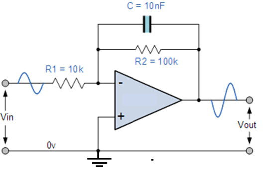
Knowing the general process would be best, but this particular configuration is the one I need an answer for. for this problem low frequency is defined as $f \ll 159$ Hz and high frequency gain is defined as $f \gg 159$ Hz.
-
$\begingroup$ assume that the op-amp is ideal, that is it has infinite open loop gain and infinite high input impedance (no current flowing into its (-) and (+) terminals). $\endgroup$– hyportnexCommented Dec 4, 2017 at 19:58
-
$\begingroup$ post this on the engineering stack exchange, there are lots of experts there on problems like this. $\endgroup$– niels nielsenCommented Dec 4, 2017 at 22:31
1 Answer
At low frequency, the capacitor acts as an open circuit. This leaves you with an opamp with just two resistors for which you can compute the gain as -10.
At the limit of very high frequency, the capacitor acts a lot like a short circuit. At this point the output of the amplifier is connected to the inverting input; with the inverting input at "virtual ground", there will be no gain.
In the general case, the gain is the ratio of the impedance of the feedback network over the feed-in network. The feedback network comprises of a parallel circuit of a resistor and a capacitor; the feed-in network in this case is just a single resistor. It follows that
$$G = -\frac{\frac{R_2}{1+j\omega R_2 C}}{R_1}$$
It is easy to see that when $\omega \rightarrow 0$ or $\omega \rightarrow \infty$, this reduces to the results I gave above. You can go a step further and look at the behavior at "large but not infinite", and "small but nonzero" values of $\omega$. If we put $R_2 C = \tau_2$, then when $\omega \tau \gg 1$ we obtain
$$G = -\frac{R_2/R_1}{j\omega\tau_2}$$
Alternatively, if we put $R_1 C = \tau_1$, then we can simplify the above to
$$G = -\frac{R_2/R_1}{j\omega R_2 C} = -\frac{1}{j\omega\tau_1}$$
This shows that the circuit is essentially acting as an integrator with time constant $R_1 C$ - that is, the current that flows through $R_1$ will charge up $C$. The presence of $R_2$ limits the gain at low frequencies (so if there is a small offset in the opamp, it will not result in the output being driven to the rail). An "ideal integrator" (with perfect components) might not even have the resistor $R_2$, but in practice most circuits will put something there for the reason I gave; but the ratio $R_2/R_1$ is often much larger - this extends the range of frequencies over which the circuit acts as a useful integrator.
-
$\begingroup$ i think that makes sense. in the case that $\omega$ does not go to 0, I get $(100k/(1+j*100k*10nF))/10k$ for the high-end frequency, which should be 10/(1+j*1ms)$. but the closest options given in the book are $1/(\omega*T_1$ and $-10/(\omega*T_2$. I'm guessing it's the second, but where does the - come from? In fact, where did it come from for the other? Is it just from the - input? Forgive my poor LaTex. $\endgroup$– SevenCommented Dec 4, 2017 at 20:52
-
$\begingroup$ Sorry yes - it's an inverting input so there is a minus sign missing in my answer... editing it in now. $\endgroup$– FlorisCommented Dec 4, 2017 at 20:53
-
$\begingroup$ "the capacitor acts as a short circuit" is one of those answers that makes me tell the students: "you're welcome to retake the exam" ;-) In the high frequency region (where's the boundary?), that circuit behaves as an integrator, not as a circuit with "no gain". $\endgroup$ Commented Dec 4, 2017 at 20:58
-
$\begingroup$ @MassimoOrtolano - your criticism is valid if the question is "how does the circuit behave". But if (as is the case here) the question is "how do I calculate the gain for frequency f", then it is a convenient shortcut. At any rate the full expression for G which I showed gives more details about what happens at intermediate frequencies. At the high frequency limit the circuit might be an integrator, but the amplitude of the output signal tends to zero. Because, of course, the integral of a high frequency signal never gets very big. Integration with an opamp makes more sense for low frequency. $\endgroup$– FlorisCommented Dec 4, 2017 at 21:06
-
$\begingroup$ If the circuit in the high frequency region behaves as an integrator, its gain is (approximately) that of an integrator. Note also the boundary between the low and high frequency regions specified in the question. Actually, integration with an op amp doesn't make sense for low frequencies, as in the sense specified in the question. Your answer would be a good answer, and I'd be happy to upvote it, were it not for the too much abused "the capacitor acts a lot like a short circuit", which is too much of an approximation here. $\endgroup$ Commented Dec 4, 2017 at 21:58

