0
$\begingroup$

For example,

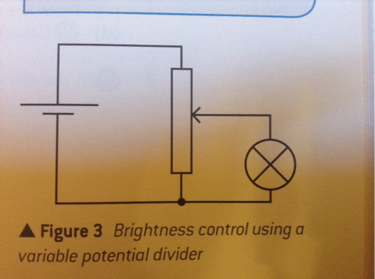
enter image description here the diagram in my text book shows a filament lamp, in series with a uniform resistive wire, which can have its voltage and current varied by moving the sliding contact, e.g., a rotatable wheel. However, why is a potential divider able to reduce the current through the filament lamp to zero, but a variable resistor in series with the filament lamp cannot reduce current to zero, I.e., there is still a very small amount of current through the lamp when a variable reisistor is used.

$\endgroup$

1 Answer 1

2
$\begingroup$

In the diagram linked, there are effectively two variable resistors, one of which is in a parallel with the lamp (the other is neither in series or parallel with the lamp). The sum of these two resistances is a constant.

enter image description here

Since the voltage across parallel connected circuit elements is identical, and since the voltage across zero resistance is zero, it is possible for there to be zero voltage across the lamp (the potentiometer is adjusted such that the parallel resistance is zero).

In the case of a series connected variable resistor (rheostat), there is no resistance in parallel with the lamp, only the series connected resistance of the variable resistor. Thus, unless the variable resistor can be adjusted to 'infinite' resistance (open circuit), the voltage across the lamp cannot be made exactly zero (though it can be made very small).

$\endgroup$
7
  • $\begingroup$ Thanks a lot for replying! I understand that voltage across parallel components is identical, and hence that if voltage is zero across the potentiometer it will be zero across the filament lamp. However, for there to be zero voltage across the potentiometer, surely adjusting the resistance of the potentiometer completely to zero is impossible? $\endgroup$
    – John
    Commented Feb 18, 2016 at 10:18
  • $\begingroup$ @John, a potentiometer is a three terminal device so there are three voltage variables, not one. There is the voltage across the element, the voltage between the wiper and one end of the element, and the voltage between the wiper and the other end. And yes, the potentiometer can be be adjusted such that the wiper is at one end of the element or the other. In the diagram above, if the potentiometer is adjusted such that the wiper is connect to the bottom end of the element, there will be zero voltage across the lamp. $\endgroup$ Commented Feb 18, 2016 at 12:24
  • $\begingroup$ If there is zero voltage across the lamp, does this mean there is therefore all voltage across the wiper. If so, why does this not mean that the wiper has an infinite resistance, so that there is no voltage for the filament lamp? $\endgroup$
    – John
    Commented Feb 18, 2016 at 13:45
  • $\begingroup$ @John, I don't understand your reasoning. With the wiper moved to the bottom, the terminals of the lamp are connected directly to each other, i.e., there is a short circuit across the lamp. I don't understand how this can be interpreted as infinite resistance. $\endgroup$ Commented Feb 18, 2016 at 13:54
  • $\begingroup$ If the slider is at the bottom, I think I'm correct in thinking that this is the same as this. So for zero voltage across the filament lamp, surely all voltage goes to R. Hence surely R must have infinite resistance? $\endgroup$
    – John
    Commented Feb 18, 2016 at 14:38

Your Answer

By clicking “Post Your Answer”, you agree to our terms of service and acknowledge you have read our privacy policy.

Not the answer you're looking for? Browse other questions tagged or ask your own question.