0
$\begingroup$

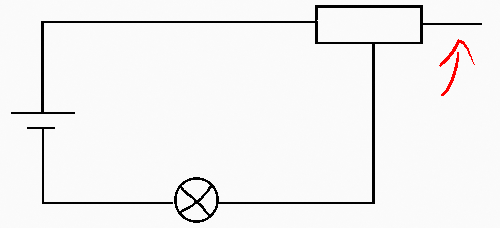
In the diagram below, the resistor has three terminals I believe. Now in this circuit, my book tells me, that only two terminals are being used (to alter the resistance by sliding the metal contact). I don't understand what happens to the third terminal. The current enters the first terminal, through the coil in the resistor, then what?

(Some) will go through the contact and into the circuit. But what if it just ignores the contact and "chooses" to go further, towards the third terminal? Then it just comes to a stop? What does this look physically? Do we connect the third terminal back in or something. Diagrams (representing PHYSICAL setups) would help.

$\endgroup$
7
  • 3
    $\begingroup$ That's like asking why the current doesn't flow out of the terminals of a disconnected battery. $\endgroup$
    – badjohn
    Commented Feb 22, 2020 at 10:32
  • $\begingroup$ Really? So you are saying that the current doesn't even bother going that way? What if I connected that third terminal to the circuit? $\endgroup$
    – El Flea
    Commented Feb 22, 2020 at 10:33
  • $\begingroup$ In practical terms - no. If you are very precise, the unconnected terminal will have a slight capacitance and a tiny current will briefly flow until enough charge builds up to prevent any more. But, if you worry about that then you should also worry that your wires are not perfect conductors either. $\endgroup$
    – badjohn
    Commented Feb 22, 2020 at 10:37
  • $\begingroup$ If the third terminal was connected then current may flow through it. It depends on what it is connected to. If you are using DC and ignore the tiny, brief flow due to the slight capacitance then current will only flow if there is a loop. $\endgroup$
    – badjohn
    Commented Feb 22, 2020 at 10:40
  • 1
    $\begingroup$ Here's an analogy that might help. Imagine that the wires are corridors in a building and the electrons are people. The battery is a slave driver with a whip forcing them along. Some may choose to go into the dead end but soon it will fill up. There won't be any continuous flow through it. $\endgroup$
    – badjohn
    Commented Feb 22, 2020 at 10:46

3 Answers 3

1
$\begingroup$

In the diagram below, the resistor has three terminals I believe. Now in this circuit, my book tells me, that only two terminals are being used (to alter the resistance by sliding the metal contact). I don't understand what happens to the third terminal.

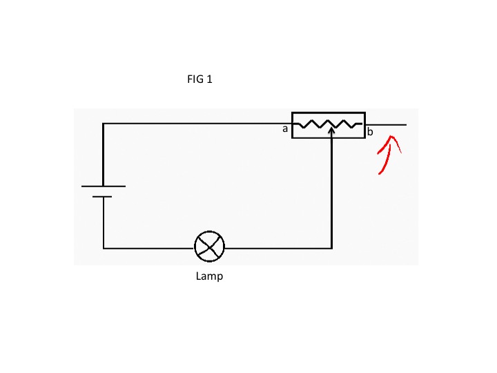
For this particular type of variable resistor, nothing happens. The third terminal is left intentionally unused. I have replicated your diagram below with additional detail (See Fig 1). The slider (arrow) can move from $a$ to $b$ (the unused terminal) to vary the voltage to the lamp. At position $a$ all of the battery voltage is across the lamp. Sliding the wiper from $a$ to $b$ reduces the voltage across the lamp (dims it for an incandescent lamp). At position $b$ the battery voltage is divided up between the lamp resistance and the variable resistor, depending on the values of each.

Not all variable resistors are set up this way. Sometimes the wiper is the third terminal and the third terminal is the output of the circuit to which a load is connected.

Now, to answer your specific questions:

The current enters the first terminal, through the coil in the resistor, then what?

Then it goes through the load (lamp in my diagram).

(Some) will go through the contact and into the circuit. But what if it just ignores the contact and "chooses" to go further, towards the third terminal?

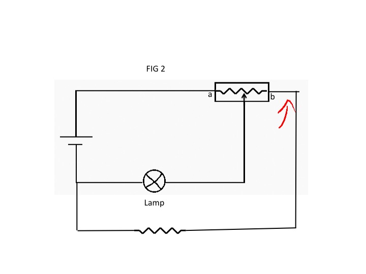
No current will go to the third terminal (i.e., leave the circuit) because it has no where to go. That does not mean, however, that there is no voltage on the third terminal. A voltmeter connected between $b$, which electrically is the third terminal, and the negative terminal of the battery will give you a voltage. So if you connected something between the third terminal and the negative terminal of the battery, current will flow (as discussed below for Fig 2).

Do we connect the third terminal back in or something.

Though it is not normally used in this type of variable resistor, there is nothing to prevent connecting something to the third terminal. See Fig 2.

Hope this helps.

enter image description here

enter image description here

$\endgroup$
1
  • $\begingroup$ What a well written answer! Even answered some of my other doubts! $\endgroup$
    – El Flea
    Commented Feb 23, 2020 at 7:36
1
$\begingroup$

Physically, a resistor is made from an electrically 'resistive' material such as carbon or carbon composite, metal or metal oxide film, connected to two terminals. When a voltage source such as a battery is connected to the terminals, charge carriers such as free electrons in the resistive material start to 'flow', resulting in an electric current $I$ given by Ohm's Law.

$I = \frac{V}{R}$

The resistance of the resistive material is measured in Ohms, $\Omega$. Typically, resistive materials are made from carbon, metal or metal oxide film. For a resistive material of length $L$ and cross-sectional area $A$, the resistance is given by:

$R = \rho\frac{L}{A}$ where

where $\rho$ is the resistivity of the material (in $\Omega.m)$.

Physically, the voltage source establishes an electric field $E$ within the resistive material, resulting in a current of density $J=\frac{I}{A} = \frac{E}{\rho}$.

For a variable resistor, or potentiometer, a third terminal is connected to a slider which intercepts the resistor at some tapping point, as shown schematically in your diagram, effectively reducing the length of the resistor and therefore the resistance between the terminal and the tapping point.

When the voltage is applied across the first terminal and the tapping point, with nothing connected to the third terminal, the electric field will only be present between the first terminal and the tapping terminal. There will be no electric field between the tapping terminal and the third terminal, so no current will flow to the third terminal. It will appear as a 'blocked path' or 'open circuit' with 'infinite resistance'.
$\endgroup$
1
$\begingroup$

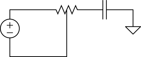
In essence, the open lead acts like a capacitor with a very small capacitance connected to ground:

When the circuit is first turned on, the voltage from the battery pushes electrons through to both of the exits from the resistor. The electrons that go to the left reach the battery, and are able to follow on with the normal DC functioning of the circuit, but the electrons that go to the right can't do any of that $-$ they get stuck at the end of the wire, and they quickly accumulate. This accumulation of charge then quickly jumps up in electrical potential, until the potential-energy hill that it generates for incoming electrons that they simply don't want to go there at all. Thus, in the steady state, no charge goes to the right.

This behaviour is exactly what you would get if you had wired a parallel-plates capacitor to that open lead, except that the plate on the left has been shrunk until it is the size of the diameter of the wire, and the plate on the right has been expanded and taken far away: it consists of the conductor that's connected to ground that is closest to the end of the open lead. This process makes the capacitance of this capacitor extremely tiny, which means that it can generate large voltages while accumulating only a tiny amount of charge, which is what accumulates at the end of the open lead.

Things are different, however, if you run this circuit in AC with an oscillating voltage source, since then you are indeed able to drive a current into and out of the open lead, so that it alternatively accumulates excesses of negative and positive charge. This is, of course, how antennas work!

$\endgroup$

Your Answer

By clicking “Post Your Answer”, you agree to our terms of service and acknowledge you have read our privacy policy.

Not the answer you're looking for? Browse other questions tagged or ask your own question.