3
$\begingroup$

The following is a question from a practice Physics GRE exam (found online at ETS's website).

The circuit shown in the figure consists of eight resistors, each with resistance R, and a battery with terminal voltage V and negligible internal resistance. What is the current flowing through the battery?

Here is the figure in question:
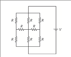
Resistors

In case the figure doesn't load, here's the problem from ETS: https://www.ets.org/s/gre/pdf/practice_book_physics.pdf, page 54, problem 68.

Since this is a GRE question I figured there was a shorter approach than a brute-force, Kirchoff's Voltage Law around every loop. I've been trying to figure out what a simpler solution would be by reducing parallel/series resistors, which currently there aren't any that can be reduced that way. Then I tried a triangle-star conversion, where I basically reduced each closed square in the diagram (each square was essentially a triangle because each had a resistor-less wire on one of the sides) but that also didn't lend itself to parallel/series reduction. I couldn't figure out another approach after that.

The correct answer is 3/2**V/R*, and an abbreviated solution I saw someone else put online (http://physicsworks.files.wordpress.com/2012/09/gr0877_solutions.pdf, problem 68, if you're interested) said to treat the problem as 3 separate 2 R resistors in parallel, but I am not sure how that works, because there are still the two horizontal resistors. Could someone explain to me either why this approach to the problem is correct or an alternative approach to the problem? Thank you!

$\endgroup$
5
  • 3
    $\begingroup$ Vote to reopen. It was a good question to begin with, since it asked why we can pretend that those two resistors don't exist. If anything, asking the OP to show more effort and describe approaches that don't work is distracting from the core issue here. $\endgroup$
    – user10851
    Commented Jul 1, 2013 at 18:55
  • $\begingroup$ I (the OP) wasn't the one who tagged this as homework, that was an edit someone else performed. Is there any way I can veto others' edits? $\endgroup$ Commented Jul 1, 2013 at 22:33
  • $\begingroup$ Hi Joshua. I see you already have figured out how to edit a post. If you haven't already done so, please take a minute to read the definition of when to use the homework tag, and the Phys.SE policy for homework-like problems. $\endgroup$
    – Qmechanic
    Commented Jul 2, 2013 at 13:31
  • $\begingroup$ @Qmechanic, so, were my edits sufficient to bring my question up to what it should be? And also I should restore the homework tag because I'm trying to understand the process rather than the answer for this problem? $\endgroup$ Commented Jul 2, 2013 at 18:24
  • $\begingroup$ @Joshua: Yes, the homework tag applies to this question (v4). $\endgroup$
    – Qmechanic
    Commented Jul 2, 2013 at 18:58

3 Answers 3

7
$\begingroup$

The voltage across either horizontal resistor is zero so they can be removed from the circuit without changing the solution.

enter image description here

This is most easily seen by simply removing the two horizontal resistors and then it's clear that the nodes the horizontal resistors connect to each have the same voltage. Thus, by Ohm's law, there is no current through either horizontal resistor since there is no voltage across either resistor.

In other words, it doesn't matter if the horizontal resistors are there or not so they can be removed without changing the solution.

You are then left with 3 identical paths with resistance 2R each.

Of course, in a real circuit, the real resistors will never be identical so, this ideal solution is only an approximation.

$\endgroup$
4
  • $\begingroup$ How can I be sure that removing the resistors in this way is a valid move and doesn't actually change the situation at hand before we judge it? $\endgroup$ Commented Jun 28, 2013 at 2:28
  • $\begingroup$ @Joshua, there's a symmetry to the circuit that suggests this move. If you "flip" the resistor network left to right, it appears unchanged. This implies that the "outside" node voltages of the horizontal resistors must be equal, etc. See, for example: physics.stackexchange.com/q/67310 $\endgroup$ Commented Jun 28, 2013 at 3:28
  • $\begingroup$ @Joshua Just a side note, they could even be short-circuited (their R=0), so you have three Rs in parallel with total R/3, and then again (in series to them) three R in parallel, total R/3. This leads to sum 2/3 R of total resistance. $\endgroup$
    – Voitcus
    Commented Jun 28, 2013 at 6:55
  • $\begingroup$ Some related videos: video1 video2 $\endgroup$
    – Ali
    Commented Jun 28, 2013 at 8:28
3
$\begingroup$

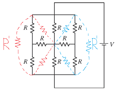
Besides Alfred Centauri's elegant solution, there is a way to use the triangle-star transformation to solve the problem. This includes transforming the two stars, each comprised of the two outer vertical and a adjacent horizontal resistor, into a triangle. This is always helpful to know because the symmetry might not be present.

enter image description here

The resulting triangles are drawn in red and blue, and the triangle of resistors is obtained from the star it encloses. All the resulting resistors have the same value

$$ R^{\prime}=\frac{RR+RR+RR}{R}=3R $$

After this it is straightforward to obtain the effective resistance

$$ \frac{1}{R_{eff}}=\frac{1}{3R}+\frac{1}{3R}+\frac{1}{2\cdot\frac{1}{\frac{1}{3R}+\frac{1}{3R}+\frac{1}{R}}} $$

which comes out as $R_{eff}=\frac{2}{3}R$ so that the current is $3V/2R$.

$\endgroup$
1
$\begingroup$

For all those who have trouble deciding which sides of the triangle (delta) to combine and have questions like these: How do you know (after having 2 triangles or "deltas", in this case, in place of your T-networks) how to collapse the triangles into the rest of the circuit so as to make it resemble an ordinary series and/or parallel circuit?

The key idea seems to be you must collapse right triangles first. Doing anything else seems to put oneself in trouble by miscalculating equivalent resistance.

The idea beneath the first is that if you combine the hypotenuse and either of the other sides, you can say the two are in parallel. The idea is that if you combine an opposite and adjacent side, you can say the two are in series.

So resistances of delta arms of triangles that replaced T-networks...those are all 3R. The remaining 2 resistors not converted into triangles are 1R.

As you redraw the geometry of your problem after simplifying triangles in about 4 steps, you should have many parallel equivalent calculations. And I only got 1 equivalent resistance calculation that was series. In the end, you must end up with Req = 6R/9. And I is easily calculated with V=IR.

$\endgroup$

Your Answer

By clicking “Post Your Answer”, you agree to our terms of service and acknowledge you have read our privacy policy.

Not the answer you're looking for? Browse other questions tagged or ask your own question.