4
$\begingroup$

In a BJT (Bipolar Junction Transistor), say NPN in common base configuration, we forward bias the Base-Emitter Junction and reverse bias the Base-Collector Junction when using a constant DC supply.

Intuitively, when I replace DC with AC, the polarity changes after every half cycle. And this means, the Base-Emitter Junction is now reverse biased and Base-Collector is forward biased. This leads the BJT to be in Reverse-Active Mode.

But, we also know, the manufacturing of transistor is made uniquely, Emitter with medium area and highly doped and Collector being of largest in area and averagely doped. And changing the direction of current should might obstruct its function.

So, is there some transistors that can go in reverse-active mode and some breakdown, or it is a general property? And if later is the answer, how does it work?

$\endgroup$
2
  • 1
    $\begingroup$ Please check out Q point. For a video lecture series I'd highly recommend " Razavi lectures "on YouTube. He is an award winning professor, Imho the best I've found on YouTube. $\endgroup$
    – Kashmiri
    Commented Jan 9, 2021 at 14:27
  • $\begingroup$ Would Electrical Engineering be a better home for this question? $\endgroup$
    – Qmechanic
    Commented Jan 9, 2021 at 15:21

1 Answer 1

7
$\begingroup$

The key is that you don't replace the DC bias with an AC signal, but you add the AC signal to the DC bias. The BJT amplifier circuits that you're studying perform this sum between the two components, and the BJT will work in the forward-active region as long as the AC signal is sufficiently small.

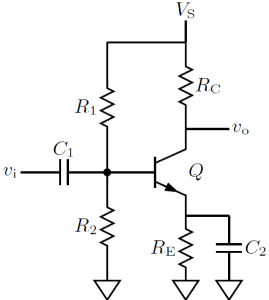
To better understand this point, let's have a look at the common emitter amplifier with self-bias circuit shown below:

Common emitter amplifer with self-bias circuit

The resistors $R_1$, $R_2$ and $R_\mathrm{E}$ define the DC operating point and the base of the BJT Q will be at a certain potential $V_\mathrm{B}$ (I shall use the convention, common in electronics, that upper case letters denote bias quantities, whereas lower case letters denote variable quantities).

Suppose that the input voltage $v_\mathrm{i}$ is initially zero. The capacitor $C_1$ will then charge at the value $V_\mathrm{B}$. If we assume that $C_1$ is sufficiently large so that its voltage doesn't change when $v_\mathrm{i}\neq 0$, we then have, by Kirchhoff's voltage law applied at the input mesh, $v_\mathrm{B} = V_\mathrm{B}+v_\mathrm{i}$. That is, when there is a signal, the instantaneous base voltage $v_\mathrm{B}$ is the sum of the DC bias and the AC signal.

Indeed, if you increase the amplitude of the input signal, the BJT will first enter the saturation region and then the breakdown region. In the saturation region the output signal is highly distorted. In the breakdown region, if the base current becomes large enough, the BJT dies of a horrible albeit quick death.

$\endgroup$
2
  • 2
    $\begingroup$ Your first line was the key :) $\endgroup$
    – Kashmiri
    Commented Jan 9, 2021 at 14:25
  • $\begingroup$ Thank you. According to high school physics, it is taught, as capacitor blocks DC and allows AC (by constantly charging and discharging). And I usually forget the last part. So with your answer, vB = VB + vi, I convinced myself like this, The capacitor is charged in first half cycle, and discharge a little in next half cycle. And VB is constant DC, so a +-vi (<< VB) does not change the bias of the junctions. Please confirm if I am right. $\endgroup$ Commented Jan 10, 2021 at 8:24

Your Answer

By clicking “Post Your Answer”, you agree to our terms of service and acknowledge you have read our privacy policy.

Not the answer you're looking for? Browse other questions tagged or ask your own question.