added 10 characters in body
Source Link
Massimo Ortolano
  • 4.9k
  • 1
  • 20
  • 32

The key is that you don't replace the DC bias with an AC signal, but you add the AC signal to the DC bias. The BJT amplifier circuits that you're studying perform this sum between the two components, and the BJT will work in the forward-active region as long as the AC signal is sufficiently small.

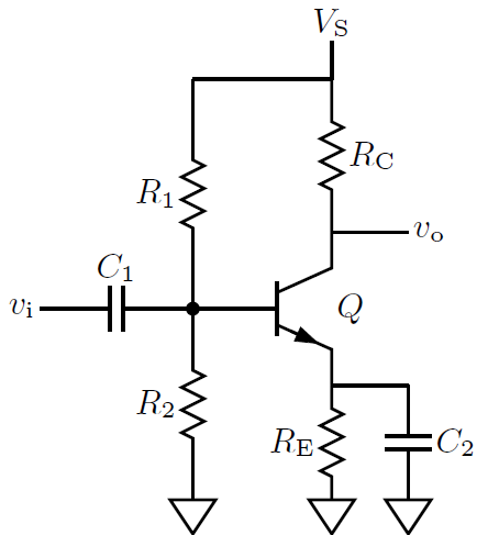
To better understand this point, let's have a look at the common emitter amplifier with self-bias circuit shown below:

enter image description hereCommon emitter amplifer with self-bias circuit

The resistors $R_1$, $R_2$ and $R_\mathrm{E}$ define the DC operating point and the base of the BJT Q will be at a certain potential $V_\mathrm{B}$ (I shall use the convention, common in electronics, that upper case letters denote bias quantities, whereas lower case letters denote variable quantities).

Suppose that the input voltage $v_\mathrm{i}$ is initially zero. The capacitor $C_1$ will then charge at the value $V_\mathrm{B}$. If we assume that $C_1$ is sufficiently large so that its voltage doesn't change when $v_\mathrm{i}\neq 0$, we then have, by Kirchhoff's voltage law applied at the input mesh, $v_\mathrm{B} = V_\mathrm{B}+v_\mathrm{i}$. That is, when there is a signal, the instantaneous base voltage $v_\mathrm{B}$ is the sum of the DC bias and the AC signal.

Indeed, if you increase the amplitude of the input signal, the BJT will first enter the saturation region and then the breakdown region. In the saturation region the output signal is highly distorted. In the breakdown region, if the base current becomes large enough, the BJT dies of a horrible albeit quick death.

The key is that you don't replace the DC bias with an AC signal, but you add the AC signal to the DC bias. The BJT amplifier circuits that you're studying perform this sum between the two components, and the BJT will work in the forward-active region as long as the AC signal is sufficiently small.

To better understand this point, let's have a look at the common emitter amplifier with self-bias circuit shown below:

enter image description here

The resistors $R_1$, $R_2$ and $R_\mathrm{E}$ define the DC operating point and the base of the BJT Q will be at a certain potential $V_\mathrm{B}$ (I shall use the convention, common in electronics, that upper case letters denote bias quantities, whereas lower case letters denote variable quantities).

Suppose that the input voltage $v_\mathrm{i}$ is initially zero. The capacitor $C_1$ will then charge at the value $V_\mathrm{B}$. If we assume that $C_1$ is sufficiently large so that its voltage doesn't change when $v_\mathrm{i}\neq 0$, we then have, by Kirchhoff's voltage law applied at the input mesh, $v_\mathrm{B} = V_\mathrm{B}+v_\mathrm{i}$. That is, when there is a signal, the instantaneous base voltage $v_\mathrm{B}$ is the sum of the DC bias and the AC signal.

Indeed, if you increase the amplitude of the input signal, the BJT will first enter the saturation region and then the breakdown region. In the saturation region the output signal is highly distorted. In the breakdown region, if the current becomes large enough, the BJT dies of a horrible albeit quick death.

The key is that you don't replace the DC bias with an AC signal, but you add the AC signal to the DC bias. The BJT amplifier circuits that you're studying perform this sum between the two components, and the BJT will work in the forward-active region as long as the AC signal is sufficiently small.

To better understand this point, let's have a look at the common emitter amplifier with self-bias circuit shown below:

Common emitter amplifer with self-bias circuit

The resistors $R_1$, $R_2$ and $R_\mathrm{E}$ define the DC operating point and the base of the BJT Q will be at a certain potential $V_\mathrm{B}$ (I shall use the convention, common in electronics, that upper case letters denote bias quantities, whereas lower case letters denote variable quantities).

Suppose that the input voltage $v_\mathrm{i}$ is initially zero. The capacitor $C_1$ will then charge at the value $V_\mathrm{B}$. If we assume that $C_1$ is sufficiently large so that its voltage doesn't change when $v_\mathrm{i}\neq 0$, we then have, by Kirchhoff's voltage law applied at the input mesh, $v_\mathrm{B} = V_\mathrm{B}+v_\mathrm{i}$. That is, when there is a signal, the instantaneous base voltage $v_\mathrm{B}$ is the sum of the DC bias and the AC signal.

Indeed, if you increase the amplitude of the input signal, the BJT will first enter the saturation region and then the breakdown region. In the saturation region the output signal is highly distorted. In the breakdown region, if the base current becomes large enough, the BJT dies of a horrible albeit quick death.
deleted 5 characters in body
Source Link
Massimo Ortolano
  • 4.9k
  • 1
  • 20
  • 32

The key is that you don't replace the DC bias with an AC signal, but you add the AC signal to the DC bias. The BJT amplifier circuits that you're studying perform this sum between the two components, and the BJT will work in the forward-active region as long as the AC signal is sufficiently small.

To better understand this point, let's have a look at the common emitter amplifier with self-bias circuit shown below:

enter image description here

The resistors $R_1$, $R_2$ and $R_\mathrm{E}$ define the DC operating point and the base of the BJT Q will be at a certain potential $V_\mathrm{B}$ (I shall use the convention, common in electronics, that upper case letters denote bias quantities, whereas lower case letters denote variable quantities).

Suppose that the input voltage $v_\mathrm{i}$ is initially zero. The capacitor $C_1$ will then charge at the value $V_\mathrm{B}$. If we assume that $C_1$ is sufficiently large so that its voltage doesn't change when $v_\mathrm{i}\neq 0$, we then have, by Kirchhoff's voltage law applied at the input mesh, $v_\mathrm{B} = V_\mathrm{B}+v_\mathrm{i}$. That is, when there is a signal, the instantaneous base voltage $v_\mathrm{B}$ is the sum of the DC bias and the AC signal.

Indeed, if you increase the amplitude of the input signal, the BJT will first enter the saturation region and then the breakdown region. In the saturation region the output signal will beis highly distorted. In the breakdown region, if the current becomes large enough, the BJT dies of a horrible albeit quick death.

The key is that you don't replace the DC bias with an AC signal, but you add the AC signal to the DC bias. The BJT amplifier circuits that you're studying perform this sum between the two components, and the BJT will work in the forward-active region as long as the AC signal is sufficiently small.

To better understand this point, let's have a look at the common emitter amplifier with self-bias circuit shown below:

enter image description here

The resistors $R_1$, $R_2$ and $R_\mathrm{E}$ define the DC operating point and the base of the BJT Q will be at a certain potential $V_\mathrm{B}$ (I shall use the convention, common in electronics, that upper case letters denote bias quantities, whereas lower case letters denote variable quantities).

Suppose that the input voltage $v_\mathrm{i}$ is initially zero. The capacitor $C_1$ will then charge at the value $V_\mathrm{B}$. If we assume that $C_1$ is sufficiently large so that its voltage doesn't change when $v_\mathrm{i}\neq 0$, we then have, by Kirchhoff's voltage law applied at the input mesh, $v_\mathrm{B} = V_\mathrm{B}+v_\mathrm{i}$. That is, when there is a signal, the instantaneous base voltage $v_\mathrm{B}$ is the sum of the DC bias and the AC signal.

Indeed, if you increase the amplitude of the input signal, the BJT will first enter the saturation region and then the breakdown region. In the saturation region the output signal will be highly distorted. In the breakdown region, if the current becomes large enough, the BJT dies of a horrible albeit quick death.

The key is that you don't replace the DC bias with an AC signal, but you add the AC signal to the DC bias. The BJT amplifier circuits that you're studying perform this sum between the two components, and the BJT will work in the forward-active region as long as the AC signal is sufficiently small.

To better understand this point, let's have a look at the common emitter amplifier with self-bias circuit shown below:

enter image description here

The resistors $R_1$, $R_2$ and $R_\mathrm{E}$ define the DC operating point and the base of the BJT Q will be at a certain potential $V_\mathrm{B}$ (I shall use the convention, common in electronics, that upper case letters denote bias quantities, whereas lower case letters denote variable quantities).

Suppose that the input voltage $v_\mathrm{i}$ is initially zero. The capacitor $C_1$ will then charge at the value $V_\mathrm{B}$. If we assume that $C_1$ is sufficiently large so that its voltage doesn't change when $v_\mathrm{i}\neq 0$, we then have, by Kirchhoff's voltage law applied at the input mesh, $v_\mathrm{B} = V_\mathrm{B}+v_\mathrm{i}$. That is, when there is a signal, the instantaneous base voltage $v_\mathrm{B}$ is the sum of the DC bias and the AC signal.

Indeed, if you increase the amplitude of the input signal, the BJT will first enter the saturation region and then the breakdown region. In the saturation region the output signal is highly distorted. In the breakdown region, if the current becomes large enough, the BJT dies of a horrible albeit quick death.

added 1007 characters in body
Source Link
Massimo Ortolano
  • 4.9k
  • 1
  • 20
  • 32

The key is that you don't replace the DC bias with an AC signal, but you add the AC signal to the DC bias. The BJT amplifier circuits that you're studying perform this sum between the two components, and the BJT will work in the forward-active region as long as the AC signal is sufficiently small.

To better understand this point, let's have a look at the common emitter amplifier with self-bias circuit shown below:

enter image description here

The resistors $R_1$, $R_2$ and $R_\mathrm{E}$ define the DC operating point and the base of the BJT Q will be at a certain potential $V_\mathrm{B}$ (I shall use the convention, common in electronics, that upper case letters denote bias quantities, whereas lower case letters denote variable quantities).

Suppose that the input voltage $v_\mathrm{i}$ is initially zero. The capacitor $C_1$ will then charge at the value $V_\mathrm{B}$. If we assume that $C_1$ is sufficiently large so that its voltage doesn't change when $v_\mathrm{i}\neq 0$, we then have, by Kirchhoff's voltage law applied at the input mesh, $v_\mathrm{B} = V_\mathrm{B}+v_\mathrm{i}$. That is, when there is a signal, the instantaneous base voltage $v_\mathrm{B}$ is the sum of the DC bias and the AC signal.

Indeed, if you increase the amplitude of the input signal, the BJT will first enter the saturation region and then the breakdown region. In the saturation region the output signal will be highly distorted. In the breakdown region, if the current becomes large enough, the BJT dies of a horrible albeit quick death.

The key is that you don't replace the DC bias with an AC signal, but you add the AC signal to the DC bias. The BJT amplifier circuits that you're studying perform this sum between the two components, and the BJT will work in the forward-active region as long as the AC signal is sufficiently small.

The key is that you don't replace the DC bias with an AC signal, but you add the AC signal to the DC bias. The BJT amplifier circuits that you're studying perform this sum between the two components, and the BJT will work in the forward-active region as long as the AC signal is sufficiently small.

To better understand this point, let's have a look at the common emitter amplifier with self-bias circuit shown below:

enter image description here

The resistors $R_1$, $R_2$ and $R_\mathrm{E}$ define the DC operating point and the base of the BJT Q will be at a certain potential $V_\mathrm{B}$ (I shall use the convention, common in electronics, that upper case letters denote bias quantities, whereas lower case letters denote variable quantities).

Suppose that the input voltage $v_\mathrm{i}$ is initially zero. The capacitor $C_1$ will then charge at the value $V_\mathrm{B}$. If we assume that $C_1$ is sufficiently large so that its voltage doesn't change when $v_\mathrm{i}\neq 0$, we then have, by Kirchhoff's voltage law applied at the input mesh, $v_\mathrm{B} = V_\mathrm{B}+v_\mathrm{i}$. That is, when there is a signal, the instantaneous base voltage $v_\mathrm{B}$ is the sum of the DC bias and the AC signal.

Indeed, if you increase the amplitude of the input signal, the BJT will first enter the saturation region and then the breakdown region. In the saturation region the output signal will be highly distorted. In the breakdown region, if the current becomes large enough, the BJT dies of a horrible albeit quick death.

Source Link
Massimo Ortolano
  • 4.9k
  • 1
  • 20
  • 32
Loading