0
$\begingroup$

enter image description here

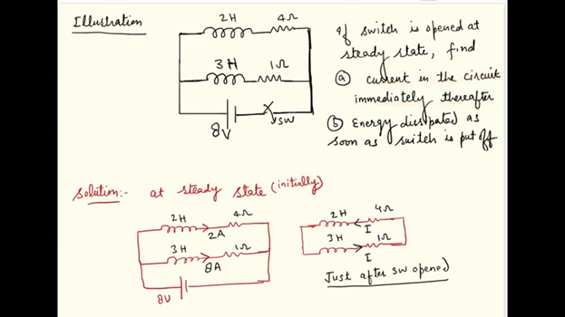
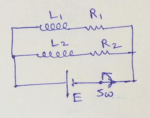
To explain my question, I wish to use the case as shown above. I am able to solve the numerical based on the above and similar cases, but still, I have a conceptual doubt regarding the workings of an Inductor.

Suppose in the case above, the battery is connected for a very long time and a steady-state is reached in the circuit. Two steady but different currents will be flowing through the two inductors, in the two branches. Now suppose, suddenly the switch adjacent to the battery is opened up. Now my doubts come into the picture:

  1. We know that the inductor doesn't allow the instantaneous change of current and flux through it, so the currents in L1 and L2 should remain the same immediately after the switch is opened up, but that is also not possible as the direction of current in the loop containing L1 and L2 cannot be in the same direction, so we reach to a contradiction. How do we resolve this conflict?

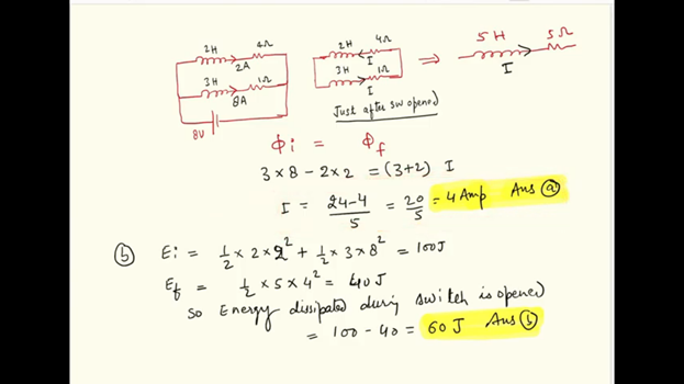
  2. In the solution to this question, textbooks apply something called "Flux Conservation" inside the remaining loop (which is left after the switched is opened up). They say that the flux through the loop containing L1, R1, L2, R2 should remain the same immediately before and after the switch is opened up. That helps us proceed and gives us some answer, but what is the conceptual basis of doing such a thing like "Flux Conservation" in the remaining loop? Why are we doing it and what is the theory behind it? Shouldn't the flux and thus the current remain conserved in both the inductors individually instead of the remaining loop? But if we assume that then that also leads to the problem I mentioned in Point 1.

  3. Even if we assume that the point 2 is right and we can apply "Flux Conservation" "inside" the remaining loop, then why are we not conserving the flux "outside" the loop in the rest of the space in the universe? Why are we conserving the flux only "inside" the loop? What is so special about the "inside"?

  4. As I understand the conceptual basis of Electromagnetic Induction (EMI) is something called "Electromagnetic Inertia". Fields like Electric and Magnetic Fields have certain inertia in them, due to which they do not allow the sudden change in themselves, which in turn leads to the effects of Electromagnetic Induction. If this understanding of EMI is right then the flux should not change inside and outside the loop in a "dt" time, but when we apply flux conservation only inside the loop then only we get the right answer.

All the thoughts above have challenged my existing understanding of EMI and Inductors. I request you to kindly help me untangle my conflicting thoughts and help me going in the right direction.

For the sake of further explaining my question, I have taken a sample problem based on the concept above, which is shown below.

enter image description here

enter image description here

The lecture corresponding to this problem can be found on the following link. https://www.youtube.com/watch?v=6MLgZIPG8i0

$\endgroup$

2 Answers 2

1
$\begingroup$

We know that the inductor doesn't allow the instantaneous change of current and flux through it, so the currents in L1 and L2 should remain the same immediately after the switch is opened up, but that is also not possible as the direction of current in the loop containing L1 and L2 cannot be in the same direction, so we reach to a contradiction. How do we resolve this conflict?

If you treat the circuit elements and circuit as ideal, and if you enforce the stipulation that inductor current must be continuous, then you reach a genuine contradiction - which tells you that one or more assumptions cannot hold for the scenario you propose.

In this particular case, I believe the best place to start untangling this problem is to add a resistor in parallel with the other branches, i.e., place resistor in parallel with the branch containing the switch and voltage source. This allows each inductor current to be continuous across the switch opening. Leave the resistor value as a parameter $R$.

Now, when the switch is opened, there remains a path for current, and you can easily see that the voltage across the added resistor, just after the switch opens, is

$$v_R(0+) = (2\,\mathrm{A} + 8\,\mathrm{A})\cdot R$$

Thus, as $R\rightarrow\infty$, it must be that the voltage across the added resistor, just after the switch opens, is arbitrarily large.

Since the the voltage across $R_1$ and $R_2$ is continuous across the switch opening, it must be that the voltage across each inductor jumps from zero to $-(10\,\mathrm{A}\cdot R - 8\,\mathrm{V})$

An arbitrarily large negative voltage across an inductor implies an arbitrarily large negative rate of change of current through, i.e., the inductor current becomes discontinuous in the limit $R\rightarrow\infty$

While this is interesting from an ideal circuit theory perspective, this isn't remotely physical since the ideal circuit element approximation isn't good here. Other effects come into play such as, e.g., inescapable stray or parasitic capacitance that will limit the rate of change of voltage, or non-linear effects such as arcing across the switch contacts as it opens.

$\endgroup$
4
  • $\begingroup$ That was an incredible response. Thanks a lot. You indeed have a very deep knowledge of this subject. Could you please help me in understanding, how we will solve a circuit like above with the assumption of ideal conditions? The solution which I have proposed above assumes "Flux Conservation". It gives the right answer, but I do not understand the conceptual basis behind it? Could you please help me understanding the conceptual basis behind flux conservation? $\endgroup$ Commented Jun 27, 2020 at 14:46
  • $\begingroup$ @DevanshMittal, I think your question about flux conservation would make a good follow-up question. Generally speaking, the community encourages asking distinct questions in separate posts. For example, see here and note the comment about linking to previous related questions. There is already a similar question here so I would link to it too, and explain why it doesn't resolve your doubt. $\endgroup$ Commented Jun 30, 2020 at 21:26
  • $\begingroup$ Thanks a lot for your kind guidance. You are an erudite and kind human being. $\endgroup$ Commented Jul 2, 2020 at 16:53
  • 1
    $\begingroup$ The post you mentioned, actually answers my question. Thanks a lot for sharing it. physics.stackexchange.com/questions/419843/… $\endgroup$ Commented Jul 2, 2020 at 16:58
0
$\begingroup$

You are probably getting confused because your question is about ideal components, which don't exist in real life.

The mathematical solution is simply that the current instantaneously drops to zero, which produces an infinite voltage for a zero length of time. None of that makes any physical sense, but that is because the math doesn't correspond to the real world situation.

What happens in real life is the the current decays fast enough to produce a large induced voltage, large enough to create a spark across the air gap when the switch is opened, and that spark is the current which completes the circuit.

Also, real inductors have non-zero capacitance, so the real-world circuit is actually an RLC circuit, and the voltage and current will oscillate and decay when the switch is opened. The "self-oscillation frequency" caused by the inductor's own capacitance is typically 1 MHz or higher, so you are not going to observe exactly what happens to the currents and voltages in real life without proper test equipment.

$\endgroup$