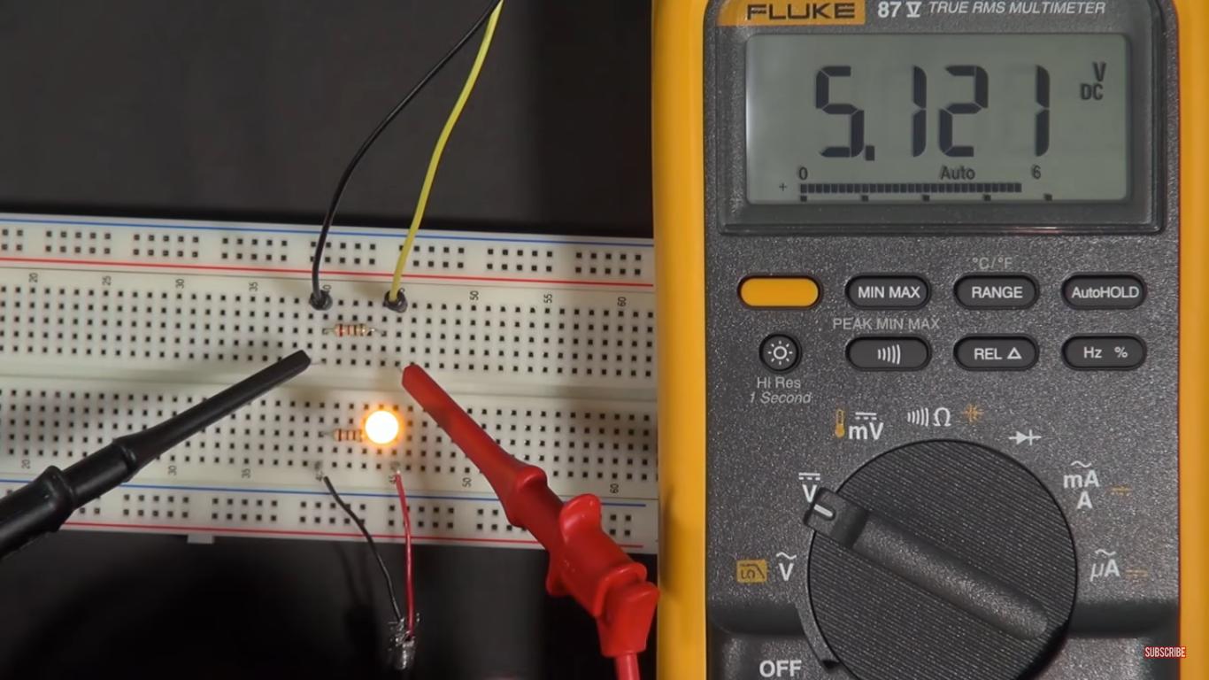
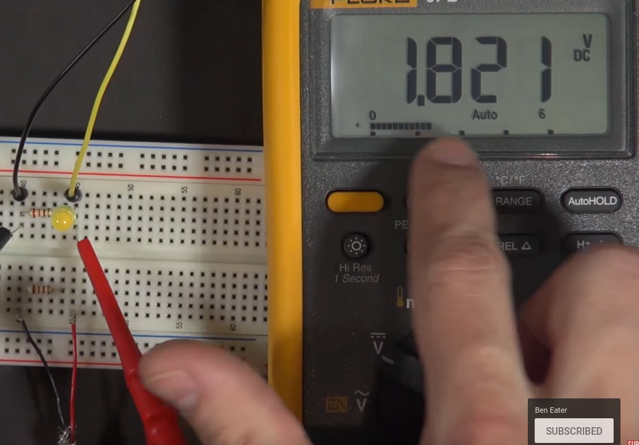
My question is originally from an youtube video, which is a tutorial series on digital electronics.
In a nutshell, He (the one in the video) has a predesigned input signal which fluctuates the voltage across the terminals, connected to a resistor. Now, he measures the voltage across it and finds that the voltage rises and drops from $5$ to $0$ volts (he measured it in the previous video of the mentioned link).
It is very clear that the resistance of the resistor is $220$ ohm. So the peak current across the resistor according to ohms law must be $23$mA. but look below the images on what he measures,
He measures a current fluctuation of $0.29$mA to $0.00$mA
He have another circuit below which is more like a battery connected to resistor and indeed finds $23$mA as the peak current.
I think there is something seriously wrong with my understanding of circuits, why must the current across the resistor be different(apart from the one that is obtained through ohms law), provided that there is a corresponding voltage between it?
One way many people think about it is in the follwing way, think of current as amount of flow of water, and voltage can be thought of as, how strong is the water being pushed, so from this analogy, if water is pushed across a narrow tube, no matter what, water will pop out the other side the same amount as it is fed into it.
Applying it, can we conclude that the input signal is not supplying enough current across the resistor?? if that is the case, then how do you correctly apply ohms law for such a resistor?
**It would be helpful if you spot where i am missing in understanding ohms law..searched a lot in internet, finally ended up here.
EDIT: I think the most problematic part in the top circuit is the input signal, i can't really think of any voltage source that makes a resistor apparently disobey ohms law, would be helpful if someone spot such one here.


