5
$\begingroup$

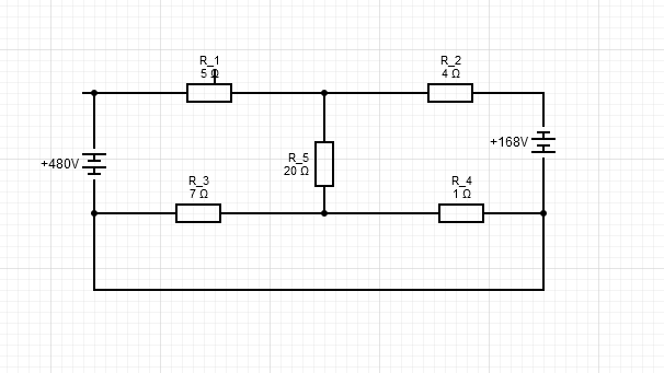
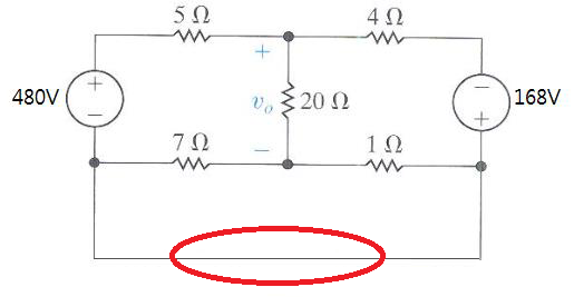
I have a trouble solving this problem. (Actually, each resistor is not parallel with the bottom wire since the voltage across each of them is different with that of wire.)

In the manual, the bottom wire(which is red circled) is simply ignored and thus can be easily solved.

I don't understand why the bottom wire can be ignored. At first, I thought it's because the node between the wire has the same voltage, making voltage difference across the wire to be 0 resulting current flowing through the wire to be 0.

I used mesh current method by myself, not ignoring the bottom wire and i got different answer, which indicated that the wire has some non-zero current flowing through it.

$\endgroup$
4
  • 4
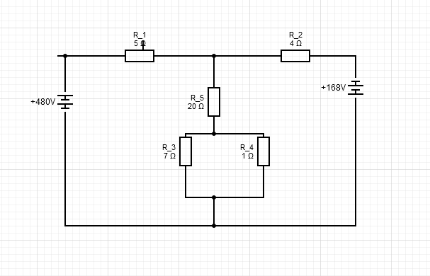
    $\begingroup$ Redraw the circuit so the 7 and 1 ohm resistors are vertical, in series with the 20 ohm, and with their bottom ends connected to each other and to both sources. Then it'll make more sense. $\endgroup$
    – hdhondt
    Commented Apr 24, 2019 at 6:07
  • $\begingroup$ If you have trouble understanding what's going on, I suggest you try inserting a resistor with resistance $r$, then analyze the circuit and at the end take the limit where $r\to 0$. $\endgroup$ Commented Apr 24, 2019 at 7:02
  • 1
    $\begingroup$ What is being asked for in the problem and what do you mean by “ignored “? $\endgroup$
    – Bob D
    Commented Apr 24, 2019 at 10:31
  • 1
    $\begingroup$ hdhondt answered the question. In the figure the node showing the junction of 7 ohm resistor and -480 V and the node showing junction of 1 ohm resistor and +168 V are in fact THE VERY SAME NODE. $\endgroup$
    – K7PEH
    Commented Apr 24, 2019 at 14:39

5 Answers 5

2
$\begingroup$

You can consider that wire as being one big node. I suggest you redraw the circuit in such a way that you replace the encircled wire with a node.

I don't understand why the bottom wire can be ignored.

It is not short circuit since it does not directly connect two terminals of the same element.

To solve for the output voltage $v_o$ I suggest you use the Millman method:

$$\varphi_1 - \varphi_3 = 480$$

$$\varphi_2 - \varphi_3 = -168$$

$$\varphi_+ (\frac{1}{5} + \frac{1}{4} + \frac{1}{20}) = \varphi_1 \frac{1}{5} + \varphi_2 \frac{1}{4} + \varphi_- \frac{1}{20}$$

$$\varphi_- (\frac{1}{7} + \frac{1}{1} + \frac{1}{20}) = \varphi_3 \frac{1}{7} + \varphi_3 \frac{1}{1} + \varphi_+ \frac{1}{20}$$

The above equations can be written in matrix form:

$$ \left[ \begin{array}{cc} \frac{1}{2} & -\frac{1}{20} & -\frac{1}{5} & -\frac{1}{4} & 0 \\ -\frac{1}{20} & \frac{167}{140} & 0 & 0 & -\frac{8}{7} \\ 0 & 0 & 1 & 0 & -1 \\ 0 & 0 & 0 & 1 & -1 \end{array} \right] \left[ \begin{array}{c} \varphi_+ \\ \varphi_- \\ \varphi_1 \\ \varphi_2 \\ \varphi_3 \end{array} \right] = \left[ \begin{array}{c} 0 \\ 0 \\ 480 \\ -168 \end{array} \right] $$

There are 5 unknowns and 4 equations, which means the system of equations is underdetermined. If we choose $\varphi_3$ as independent variable, the solution to the above equation is:

$$ \left[ \begin{array}{c} \varphi_+ \\ \varphi_- \\ \varphi_1 \\ \varphi_2 \end{array} \right] = \left[ \begin{array}{c} \frac{180360}{1663} \\ \frac{7560}{1663} \\ 480 \\ -168 \end{array} \right] + \left[ \begin{array}{c} 1 \\ 1 \\ 1 \\ 1 \end{array} \right] \varphi_3 $$

The output voltage is then

$$v_o = \varphi_+ - \varphi_- = 103.9 \text{ V}$$

Although the potential $\varphi_3$ is independent variable, it does not affect voltage calculation since it cancels out when subtracting potentials. For this reason we usually set one potential (any one!) to zero which mimics ground connection and makes matrix manipulation much easier. I suggest you solve this problem by taking some other potential as independent variable, you should get the same final result.

$\endgroup$
1
$\begingroup$

enter image description here

I suggest superpostion theorem to solve multiple source circuits

$\endgroup$
0
$\begingroup$

Just because a wire forms an equipotential structure does not mean there is no current. Otherwise, current wouldn't flow from the 480 V source + point to the beginning of the 5 $\Omega$ resistor. Don't worry about the non-zero current. Pay attention to the question the problem is asking (which you haven't shared with us).

$\endgroup$
-1
$\begingroup$

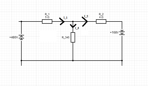
The following three circuits are equivalent: enter image description here

enter image description here

enter image description here

Resistances given: $(R_1, R_2, R_3, R_4, R_5)=(5,4,7,1,20)\ \Omega$; batteries $(E_1, E_2)=(480, 168) \ Volt$.

The resistance in the middle $R_{345}=R_5+\frac{R_3 R_4}{R_3+R_4}$.

I think you want the voltage drop across $R_5$ which is $U_5=I_5 R_5$. Use Kirchhoff's laws to obtain a system of three equations.

$ \left\{ \begin{array}{l} upper\ junction\\ left\ loop \\ right\ loop \end{array} \right\} $

$ \left\{ \begin{array}{l} I_1=I_2+I_5\\ E_1-R_1 I_1 -R_{345}I_5=0 \\ E_2+R_{345} I_5 - I_2 R_2=0 \end{array} \right\} $

Solving for $I_5$ gives $$R_5 I_5=R_5\cdot\frac{R_2E_1-R_1E_2}{R_1R_{345}+R_1R_2+R_2R_{345}}=103.909\ V$$

$\endgroup$
-3
$\begingroup$

Listen brother....if its looked in one perspective the point made by you is the ignored wire... actually its not ignored if it is a perfect conductor then the whole resistance R would be equal to zero this is one of the point which strikes my mind after looking into this question....

Hope you have got your answer

$\endgroup$

Your Answer

By clicking “Post Your Answer”, you agree to our terms of service and acknowledge you have read our privacy policy.

Not the answer you're looking for? Browse other questions tagged or ask your own question.