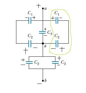
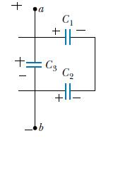
Please consider the circuit diagram below, in particular, look at the capacitors enclosed by the green loop.

*Note that the green loop and the (+) and (-) charges on the plates were drawn by me, the original circuit has none of these.
Is the charge distribution on the plates correct? The two capacitors in the green loop have a + and - plate connected by a wire, which by definition should be in series. The three -s that joins up at point d and evenly distribute itself (split) into two paths and adds charge to the two plate near point b (sorry for poor terminologies here)
But the book treats the green loop capacitors in parallel, which must imply the configuration.

I am awfully confused how $\ C_1$'s right (+) plate managed to induce $\ C_2$'s right plate to (-) and how the left plate of $\ C_2 $ has (+) plate when it's connected to the negative terminal of the battery.
Also, I've noticed that a lot of people often just attack these problems based on the geometry of the circuits and I think they would make the same mistake as my book.
