1
$\begingroup$

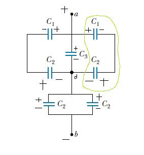
Please consider the circuit diagram below, in particular, look at the capacitors enclosed by the green loop.
enter image description here

*Note that the green loop and the (+) and (-) charges on the plates were drawn by me, the original circuit has none of these.

Is the charge distribution on the plates correct? The two capacitors in the green loop have a + and - plate connected by a wire, which by definition should be in series. The three -s that joins up at point d and evenly distribute itself (split) into two paths and adds charge to the two plate near point b (sorry for poor terminologies here)

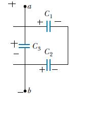
But the book treats the green loop capacitors in parallel, which must imply the configuration.
enter image description here

I am awfully confused how $\ C_1$'s right (+) plate managed to induce $\ C_2$'s right plate to (-) and how the left plate of $\ C_2 $ has (+) plate when it's connected to the negative terminal of the battery.

Also, I've noticed that a lot of people often just attack these problems based on the geometry of the circuits and I think they would make the same mistake as my book.

$\endgroup$

1 Answer 1

3
$\begingroup$

Your charge distribution is correct, though I usually don't focus on using a "correct" $\pm$ distribution in capacitors--if your sign is incorrect, you get a negative value of charge on the + plate. No biggie. In complex situations, it is sometimes even impossible to predict cjarge distribution without solving the circuit.

And your book is incorrect. $C_1-C_2$ are in series, though the entire branch is in parallel with $C_3$ and its opposite branch.

Parallel is when the current is split, while series is when current is constant. Series is a single wire with an in and an out, with components along the wire. Parallel is when there are many wires with their ends twisted together. Current goes in/out through the twisted ends.

You seem to have grasped that, though :)

Out of curiosity, which book is this? (the capacitors look like they're from Resnick)

$\endgroup$
2
  • $\begingroup$ I think they are, but they have no solutions. I grabbed from another university's website lol. But how do you know whether it is in series/parallel if you don't do what I do? Because the geometry of this circuit could be very misleading as many people would fall for. $\endgroup$
    – Lemon
    Commented May 4, 2012 at 18:09
  • $\begingroup$ @jak look at my wires explanation. Here, you have one wire threading through $C_1,C_2$. Current goes in one end and out the other. No other inlets/outlets. So series. Just check if an ant walking down one end is guaranteed to come out the other, and will pass each component exactly once during its journey. $\endgroup$ Commented May 4, 2012 at 18:40

Your Answer

By clicking “Post Your Answer”, you agree to our terms of service and acknowledge you have read our privacy policy.

Not the answer you're looking for? Browse other questions tagged or ask your own question.