0
$\begingroup$

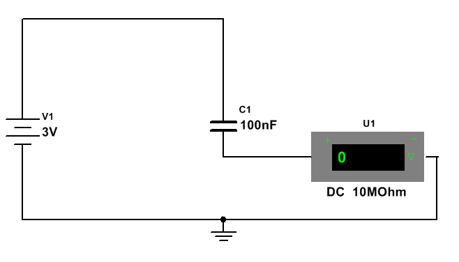
During my circuit design I came across unusual circuit as shown below:

enter image description here

At first glance this looks trivial however if you tinker a bit with it you will find voltmeter readings that are hard to explain. So for the circuit as it stands above all seems to be clear, capacitor slowly charges to 3V through voltmeter huge 10MOhm resistor. After it reaches steady-state it has equal number of charges on each plate but with opposite sign. Now let's unplug this capacitor and plug it back inversely so the previously negatively charged plate is on battery + side. What happens is voltmeter now shows +6V and slowly discharges to 1.5V. Here is the list of my questions:

  1. If you apply KVL to the newly created circuit it make sense. We have: $$ -3 - 3 + Vu1 = 0 $$ $$ Vu1 = 6V $$ But let's think of it in terms of capacitor charges. What we did is we connected negatively charge plate to positive terman of the battery. So I would rather expect it to quickly (because o the absence of any resistance) disolve alll nagative charge and gain positive ones therefore lowering capacitor pottential to 0 - since second plate slowly (due to 10Mohm resistor of voltmeter) discharges its positiive charge. So we have a situation in which right after the flip one side is +Q and other also has +Q so capacitor net potetnial shall be 0 in my opinion. Where is the mistake in my understanding?

  2. Second thing is, why it stops at 1.5V. For this is have no explanation.

PS: All I am describing is real circuit, the schematic may suggest I simulate it but this is not the case.

$\endgroup$
2
  • $\begingroup$ What type of capacitor were you using? Was the charging current variation with time as expected? What is the model number of your voltmeter? $\endgroup$
    – Farcher
    Commented Jun 2, 2018 at 9:41
  • $\begingroup$ Simple ceramic capacitor 2.2uF. Voltmeter type is cheap UNIT-T M690... not important since I see the same thing on my scope. $\endgroup$
    – DannyS
    Commented Jun 2, 2018 at 10:00

2 Answers 2

0
$\begingroup$

I can give you an answer to Question 1 but not to question 2.

enter image description here

After the initial charging the cinal state of the capacitor is that it has a potential difference of $3\, \rm V$ across it and a charge $\pm Q$ on the two plates as in the left hand diagram.

When you remove the capacitor from the circuit it still has a potential difference of $3 \,\rm V$ across it with the plate with the $+Q$ charge on it at the higher potential.

Reconnecting the capacitor means that the input terminal to the voltmeter is $6\,\rm V$ as shown in the right hand diagram with there being a potential difference of $3 \,\rm V$ across the capacitor.

So I would rather expect it to quickly (because $0$ the absence of any resistance) dissolve all negative charge and gain positive ones therefore lowering capacitor potential to $0$ - since second plate slowly (due to 10Mohm resistor of voltmeter) discharges its positive charge.

No. The positive charges on one of the capacitor plates is held there by the negative charge on the other plate (and vice versa).
So if you want to neutralise ("dissolve") those negative charges you must simultaneously do the same for the positive charges. However although there is no resistance in the top part of the circuit there is in the bottom part - the resistance of the voltmeter.
This means that the who circuit behaves as though there is a battery, a capacitor and a resistance of $10 \,\rm M\Omega$ in the circuit and so the time constant of the circuit is still one second.

Your second question is more problematic and without actually "playing" with the circuit I cannot give you a reason for what has happened.
In your circuit the voltmeter is acting as an ammeter with the reading on the display in $10^{-7}\,\rm A$ so you seem to have a steady current of $1.5 \times 10^{-7}\,\rm A$ flowing through the circuit which suggests that the capacitor might be defective?

You might try:

  • using another capacitor
  • after disconnecting the charged capacitor put it straight across the terminals of the voltmeter/CRO.
$\endgroup$
14
  • $\begingroup$ First of all I think on the right hand side schematic the voltage on cap should be -3V since it was reversed. What I don't understand is this: if we have +/- Q on both plates of capacitor and we suddenly connect positive terminal to $$0V$$ why the voltage of the capacitor doesn't decrease to -Q but is rather -2Q? For example, we charged capacitor to 2V now positive termanal of it is shorted to 0V the other one is left as it was. The voltage on cap is -4V not -2 $\endgroup$
    – DannyS
    Commented Jun 2, 2018 at 12:29
  • $\begingroup$ @DannyS You must use the term potential difference (ie it is one potential relative to another) not voltage otherwise there can be confusion. The connecting wire at the top is always 3 V higher than the connecting wire at the bottom due to the presence of the battery. You now add the negative plate of the capacitor to the top wire so that plate is 3 V higher than the bottom wire. The positive plate of the capacitor is 3 V higher than that of the negative plate. The positive plate is therefore 6 V higher than the bottom wire. $\endgroup$
    – Farcher
    Commented Jun 2, 2018 at 12:36
  • $\begingroup$ Is it okay to think of capacitor charged to 4V like it has +2V on one plate and -2 on other one so the potential between them is 4V? $\endgroup$
    – DannyS
    Commented Jun 2, 2018 at 12:49
  • $\begingroup$ @ Yes. A potential difference of 4 V across the two plates means that relative to some zero of potential, the potential of one plate is -400 V and the potential of the other plate is -404 V, or +321 V and +317 V, etc. $\endgroup$
    – Farcher
    Commented Jun 2, 2018 at 13:02
  • $\begingroup$ Here is good example of my problem I think i63.tinypic.com/zu14as.png The cap is initialy charged to 4.4V when Q1 goes ON it shorts C1 left plate to ground making its voltage -4.4V here is the question WHY? Why if we short left plate to ground, therefore lowering its potential from +2.2 to 0 the cap net voltage isn't -2V which is what's left on left hand side plate? $\endgroup$
    – DannyS
    Commented Jun 2, 2018 at 13:14
0
$\begingroup$
  1. You are connecting only one terminal of the capacitor, so no current can flow and no discharge occurs.
  2. It must be a fluke of your voltmeter. The voltage should descend to 0V again.
$\endgroup$
2
  • $\begingroup$ Completely wrong, I have two terminals connected as you can see on the schamtic. As for the fluke of my voltmeter well it must also be the case of my scope since it shows the exact same result! $\endgroup$
    – DannyS
    Commented Jun 2, 2018 at 9:57
  • $\begingroup$ If politeness is not required: you are "completely wrong" to expect a single plate to "quickly disolve alll nagative charge and gain positive ones therefore lowering capacitor pottential to 0". Why did you do this silly experiment in the first place ? $\endgroup$
    – my2cts
    Commented Jun 2, 2018 at 10:11

Your Answer

By clicking “Post Your Answer”, you agree to our terms of service and acknowledge you have read our privacy policy.

Not the answer you're looking for? Browse other questions tagged or ask your own question.