Just to follow on from the answer given by @JohnRennie.
Those unlabelled triangle in your diagram indicate that those nodes are at the same constant potential which is often chosen to be zero volt as in the case of your circuit diagram.
As far as your circuit diagram is concerned it is exactly the same as if you had connected the two triangles together with a line but there is extra information in that looking at the CRO traces those triangles are assumed to be at a potential of $0\,\rm volt$ and other potentials are measured relative to those unlabelled triangle nodes.
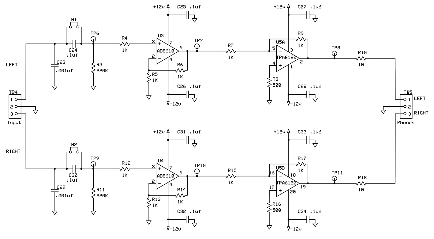
The use of such a symbol reduces the complexity of a circuit diagram as the one below for a Precision Stereo Headphone Amplifier.

Just think what the diagram would look like if all the unlabelled triangles were connected together with lines as were the triangles labelled $+12\,\rm V$ and the triangles labelled $-12\,\rm V$.
I have chosen this diagram to show that the triangle can be labelled to show its potential relative in this case to the unlabelled triangles which are to be taken as being at zero volts.
So in this diagram some nodes are all at a potential of $+12\,\rm V$ and other nodes are all at a potential of $-12\,\rm V$ relative to the unlabelled triangles.
The symbol ┴ (inverted T) is sometimes used to designate zero volts but with a label also a stated fixed potential as shown in this diagram with an upright T.

In this diagram there is the familiar earth/ground (GND) symbol which I cannot reproduce as a text symbol and that is taken as being at a potential of zero volts.


