0
$\begingroup$

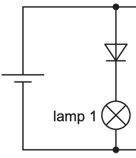
Consider the following diagram

enter image description here

Here, the diode is in forward bias, and allows current to flow. However, I am slightly confused why this is the case. A diode is defined to only allow current to flow from the anode ( Positive ) to the cathode ( Negative ). When drawing a diode, the cathode is the line and the anode the base of the triangle.

Conventional current flows from the positive terminal to negative terminal, but in reality the electrons flow vice versa. Hence, considering the above diagram, shouldn't the electrons not be able to flow through the diode? The only way I can see around this, is that diodes are also drawn, considering conventional current. Is this correct?

$\endgroup$
3
  • $\begingroup$ To avoid confusion, state and mark explicitly the $+$ and $-$ terminals of the battery on the diagram. $\endgroup$
    – hyportnex
    Commented Nov 13, 2023 at 22:55
  • 3
    $\begingroup$ The only way I can see around this, is that diodes are also drawn, considering conventional current. Is this correct? Yes. $\endgroup$
    – Farcher
    Commented Nov 13, 2023 at 23:15
  • 1
    $\begingroup$ Notice how part of the diode symbol looks like an arrowhead? The arrow points in the direction that conventional current is allowed to flow. $\endgroup$ Commented Nov 14, 2023 at 3:49

1 Answer 1

1
$\begingroup$

Yes diodes are drawn considering the conventional current. The cathode is the negative side (the side that was heated in 19th century cathode ray tubes to help the process of releasing electrons). The current opposite to the flow of electrons will go from anode to cathode.

$\endgroup$

Your Answer

By clicking “Post Your Answer”, you agree to our terms of service and acknowledge you have read our privacy policy.

Not the answer you're looking for? Browse other questions tagged or ask your own question.