0
$\begingroup$

Potentiometer circuit to compare EMF of two cells

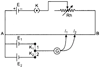
When key 1 (or 2) of the secondary circuit is connected, then for the null point, current through the galvanometer must be zero. But what I don't understand is why the cell $E_1$ (or $E_2$) of the secondary circuit doesn’t generate a current of its own despite there being a potential difference across its ends?

(This is from an experiment to compare the EMFs of two cells $E_1$ and $E_2$. Only one of these cells is connected at a time.)

$\endgroup$
2
  • $\begingroup$ Could you show the missing information on the right of the circuit about $l_1$ and $l_2$ and the procedure (when it is the right way up)? $\endgroup$
    – KDP
    Commented Sep 22 at 5:38
  • $\begingroup$ Edited to include the right side $\endgroup$
    – Navs
    Commented Sep 22 at 6:01

3 Answers 3

1
$\begingroup$

The primary cell creates a potential difference between $A$ and $B$. If we divide this by the resistance $R_{AB}$ of the potentiometer wire, we get the magnitude of current in the anticlockwise direction. This is a fixed value and does not depend on the secondary circuit.

At the same time, the secondary cell creates a voltage between $A$ and $P$, where $P$ is the point on the potentiometer wire where the galvanometer is connected. If we divide this by the resistance $R_{AP}$ of the segment $AP$ of the potential wire, we get the magnitude of current in the clockwise direction.

The resistance of a wire segment is proportional to its length:

$$R_{AP} = R_{AB}\cdot\frac{AP}{AB}$$

As the length of $AP$ varies, the resistance $R_{AP}$ also varies. At one point, the value of $R_{AP}$ becomes such that the current generated in the clockwise direction (by the secondary cell) becomes equal to the current generated in the anticlockwise direction (by the primary cell).

The length of the wire segment $AP=l_1$ is noted down, allowing us to calculate $R_{AP}$ (we already know $R_{AB}$ and $AB$). We repeat the experiment with the other secondary cell and get a reading $AP=l_2$. Since the anticlockwise current generated by the primary cell in both cases is the same, the counterbalancing clockwise current generated by $E_1$ and $E_2$ must be the same.

The magnitudes of the currents are given by:

$$\frac{V}{R_{AB}} \text{(anticlockwise)} = \frac{E_1}{R_{AP1}} \text{(clockwise)}$$ $$\frac{V}{R_{AB}} \text{(anticlockwise)} = \frac{E_2}{R_{AP2}} \text{(clockwise)}$$

From which we can derive:

$$\frac{E_1}{E_2} = \frac{R_{AP1}}{R_{AP2}} = \frac{l_1}{l_2}$$

Which is the entire purpose of the given circuit.

Note: Since the anticlockwise and clockwise currents cancel out, it is technically incorrect to treat them like two separate currents. Instead, we say that the net current is zero. Think of this separation of currents as a shorthand for calculation rather than as a rigorous description.

$\endgroup$
2
  • $\begingroup$ Is that the reason why there is no current in the secondary circuit. Do to there being no net current ( clockwise and anticlockwise cancelling out)? $\endgroup$
    – Navs
    Commented Sep 23 at 2:31
  • $\begingroup$ I have edited my answer to include a lot more clarifying details. But the TL;DR is: "Yes, the anticlockwise and clockwise currents cancel out so it appears as if the secondary cell is not generating any current." $\endgroup$
    – Amogh
    Commented Sep 23 at 5:23
0
$\begingroup$

If you connect the contact close to the end A of the potentiometer resistance wire, the battery E1 (or E2) will discharge. If you connect the contact close to B then, assuming the battery E is strong enough, it will drive current backwards through E1 as if it was trying to charge it.

There is a point L in between, where there is no current through E1. The voltage between A and L is strong enough to prevent current flowing forward through E1, but not strong enough to push current in the reverse direction through E1. This means the voltage across AL is exactly equal to the voltage across the battery E1, and it is detected by the galvanometer G reading zero.

When there is no current through E1 then it doesn't affect what is happening in the rest of the circuit. That means that the voltage drops from A to B at the same rate (of volts per centimetre) all the way along the wire.

When you measure the distance AL and you know the voltage of E1, you can work out how many volts per centimetre there are along the potentiometer resistance wire. If you know how many volts per centimeter there are (because you just did it with a known E1) then after measuring the distance along AL you can work out the voltage (to find E2).

$\endgroup$
0
$\begingroup$

Short answer:

The top loop is effectively a battery with a variable voltage. When the circuit is in equilibrium at either step, and the current through $\text{G}$ is zero, we effectively have a simple circuit with one loop with two equal batteries facing in opposite directions, trying to drive the current in opposite directions, and neither wins with a net current of zero. A water analogy would be to have two equal pressure pumps drawing from the same reservoir with their discharges connected by a hose, so they are trying to drive a water current in opposite directions through the hose. Since there is equal pressure at both ends of the hose, there is no water flow in the hose.

Detailed description of the circuit:

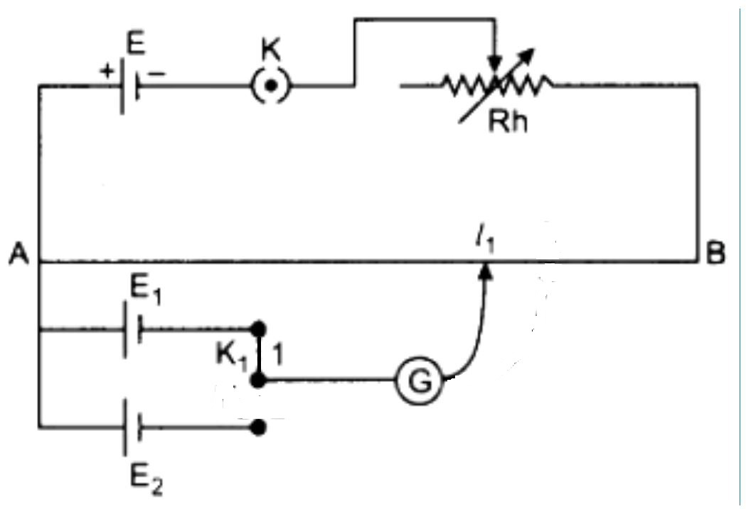
Step 1
enter image description here

First, consider the top loop in isolation. The total resistance of the top loop is $R_T = R_h + R_{\text{AB}}$ where $R_{\text{AB}}$ is the resistance of the length of the wire going from $\text{A}$ to $\text{B}$. Define the voltage of the left side of the circuit as zero so $V_{\text{A}} =0$, and the positive terminals on the left of all the cells are also zero. The top loop with sliding contact $l_1$ is a voltage divider circuit, and the voltage at the sliding contact is given by $ \Delta V = R_{\text{A} l_1}/R_{T}$. As the sliding contact is moved from $\text{A}$ to $\text{B}$, the voltage drops at the contact point. When the voltage drops to the same voltage as the negative terminal of cell $\text{E}_1$, the voltage on either side of Galvanometer $\text{G}$ is equal, so there is no potential difference across $\text{G}$ and no current flow through $\text{G}$. At this point, we have:

$$V_{L_1} = \frac{ R_{\text{A} l_1}}{R_{T}} = V_{\text{E}_1} \implies \frac{ R_{\text{A} l_1}}{ V_{\text{E}_1}} = R_{T} \tag{1}\label{eq:1}.$$

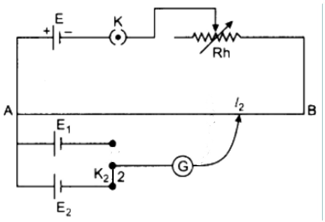
Step 2
enter image description here

Now, cell $1$ is disconnected, and cell $2$ is connected to the circuit. The slider is moved until there is no current through $\text{G}$, and this indicates that the voltage at the slider contact point is now equal to the voltage on the negative terminal of cell $\text{E}_2$. We now have:

$$V_{L_2} = \frac{ R_{A l_2}}{R_{T}} = V_{\text{E}_2} \implies \frac{ R_{A l_2}}{ V_{\text{E}_2}} = R_{T} \tag{2}\label{eq:2}.$$

We can equate equations $\eqref{eq:1}$ and $\eqref{eq:2}$ and obtain:

$$\frac{ R_{\text{A} l_1}}{ V_{\text{E}_1}} = \frac{ R_{\text{A} l_2}}{ V_{\text{E}_2}}$$

$$ V_{\text{E}_2} = V_{\text{E}_1} \frac{ R_{\text{A} l_2}}{ R_{\text{A} l_1}} = V_{\text{E}_1} \frac{ l_2} {l_1}.$$

This allows us to determine the unknown voltage of $\text{E}_2$ knowing only the value of cell $\text{E}_1$ and the ratio of the lengths $l_1 $ and $l_2$. The working principle of the circuit depends on the voltage at the slider contact being equal to the voltage of the connected cell so that there is no current flow through $\text{G}$ and, therefore, no current flow through the connected cell. The voltage at the slider provides a counter-motive force to the connected cell and prevents any current from flowing through the connected cell because a current requires a voltage difference to drive it. When the circuits are balanced at both steps, the current in the top loop is the same at both stages, and the lower loop makes no difference to conditions in the top loop because there is no current flow in the lower loop (at equilibrium).

$\endgroup$

Your Answer

By clicking “Post Your Answer”, you agree to our terms of service and acknowledge you have read our privacy policy.

Not the answer you're looking for? Browse other questions tagged or ask your own question.