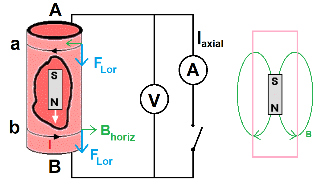
You make a good argument that there should be a Hall voltage across a conducting ring which is shorter than the falling magnet, and that the Hall voltage for the magnet-is-entering eddy current should have the same sign as the Hall voltage for the magnet-is-exiting eddy current. But I don’t think this logic extends to a Hall voltage across the entire conducting pipe, because that sustaining that voltage would require an electric field in regions of the pipe where the eddy current and the corresponding Lorentz force are zero.
I would expect a long magnet falling through a short ring to produce your Hall voltage while the end of the magnet was entering or leaving the ring, but not during the “steady state” period where the body of the magnet is moving through the ring.
For your illustrated setup, where a short magnet falls through a long pipe, I would expect your voltmeter to measure transient Hall voltages as the two ends of the magnet entered and exited the two ends of the pipe. It is not obvious to me whether those four “pulses” of Hall voltage would be the only signal in the detection circuit you’ve shown, and therefore observable using a charge-integrating detector, or whether the field-cancelling motion of charges in the zero-eddy sections of pipe would send “counter-pulses” to your circuit, so that you would have to look for transients.
I used to teach an introductory lab where we measured something like the currents $I_a$ and $I_b$ by having the students shove a bar magnet through a solenoid. (It was not a great lab. Without fail, the students would connect their solenoid to the DC power supply instead of the oscilloscope, with the bar magnet inside, which gave them a fifty-fifty chance of reversing the polarity of their “permanent” magnet.) I can imagine adapting this idea to make a practical implementation of your experiment. A thin copper cylinder, probably with its height comparable to its diameter, with a narrow slit cut in it, and the two sides of the slit connected via low-inductance and low-resistance cable to an ammeter, to measure $I_a$. On the opposite side of the ring from the slit, your Hall voltmeter, connected to the to and bottom of the slit. Your moving magnet should be a good fit to the pipe, and perhaps mounted on some non-magnetic motion stage, so that its velocity can be well-controlled.

