0
$\begingroup$

Math and statics weakling here trying to do some... math and statics. I have an experiment where I'm trying to measure forces along 2 axes. I currently have a setup that I think might give me the data I need to derive these values, but I'm not entirely confident it's possible nor do I know how to do so. I've also devised of a variant which makes more sense to me but I want to avoid unnecessary work for obvious reasons.

test rig

S1 through S3 are kitchen scales, the circle at the top is where the external vertical (down) and horizontal forces are applied, V1 is the vertical member of the experiment and it's attached to a horizontal base which is set on top of the scales. A1 & A2 don't physically exist, but I added them in the drawing as I suspect they'll be required in some explanations. My current setup just uses S1 and S3, and their distances to the vertical member are unequal. So I guess my first question is: does this configuration provide sufficient data to derive the two forces, and if so then how?

If not, then would adding the 3rd scale directly beneath V1 do so? If I'm not mistaking, the vertical force is the sum of the forces read by the scales minus the difference between S1 and S3. The horizontal forces being based on the law of the lever where S2 is the fulcrum and the difference between S1 and S3. Is that correct? This is somewhat warping my mind because in actuality I was considering ripping out the load cells from the scales with two of them from each scale being placed at S2, with the remaining load cells from one the scales placed at S1, and the remaining scale's load cells placed at S3 therefore if I went that route I'd have only 2 readings rather than 3. In which case vertical force would be the sum of the values minus their difference, and the horizontal force would follow the lever law and their difference.... I think. Maybe.

This is all assuming the rest mass of the setup has been nulled by using the tare function on the scales. I'd also like to note that the center of mass is offset from the vertical member and is pretty close to the horizontal base, but I don't think that matters. Correct? Also, the setup is fairly stiff and the physical deflections are negligible.

Answers very much appreciated!

$\endgroup$
2
  • $\begingroup$ Kitchen scales and similar devices measure the load in only 1 direction. So having 3 scales acting in the vertical direction will not measure the horizontal load (nor will they resist the horizontal load). $\endgroup$
    – JohnHoltz
    Commented Jan 18, 2019 at 0:02
  • $\begingroup$ JohnHoltz, I did have an issue with the test setup sliding on the surface of the scales so I affixed it to prevent movement, but if what you say is true then even then I'm unable to measure the horizontal force. In which case would I have to affix a pivot somewhere such as at S2? Then of course, I would not be able to measure the vertical force. I did just try to verify this by applying just a horizontal force and the value increased on one scale with the other indicating an inverse value. Therefore it seems to be able to measure horizontal forces. $\endgroup$
    – mes
    Commented Jan 18, 2019 at 0:54

1 Answer 1

0
$\begingroup$

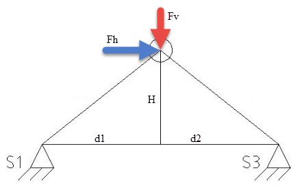
Using your suggestion (from a comment) about affixing the frame to one of the scales to prevent sliding horizontally, then it is theoretically possible to determine the horizontal and vertical forces. This is possible if the horizontal force is located at some distance above the scales (H).

$$\sum vertical\;force, \; Fv = S1+S3$$ $$\sum moments\;about\;S3, \;(d1+d2)*S1+H*Fh-d2*Fv=0$$

The first equation gives the vertical force directly (just S1+S3). The second equation can be solved for Fh to give the horizontal force: $$Fh=\frac{d2*Fv-(d1+d2)*S1}{H}$$

My only concern is whether the horizontal force on the scale is interfering with the measurement of the vertical force. You should do some tests to confirm if that is a problem or not.

measure forces

$\endgroup$
3
  • $\begingroup$ Thank you for your response. Your equation for deriving Fh looks nice and simple, but I must admit that I don't really understand how it works (like I said, I'm a math weakling). At first I also didn't understand how Fv could simply be the sum of S1 and S3, but I think it clicked now, but I assume d1 and d2 must be equidistant for it to hold true. I will go ahead and test this next week and check for interference as you suggest. If it doesn't work I'll devise a setup that measures the forces more directly in their respective axes. $\endgroup$
    – mes
    Commented Jan 18, 2019 at 7:12
  • $\begingroup$ JohnHoltz, I got around to trying your equations. I'd just like a little clarifications, if you would be so kind. In your diagram, you show Fh pointing towards S3, which makes the value at S1 show negative (at least in some of my experiments), and in your equation you are multiplying other values by it, which gives me a negative value. Why is it multiplied by S1 rather than S3? Also, in my calculations, should I be converting grams (which is what the scales report) into Newtons? Doing this seems to be the only way I get reasonable values for Fh. Thanks! $\endgroup$
    – mes
    Commented Jan 24, 2019 at 4:22
  • $\begingroup$ A negative value for S1 means the frame is trying to lift off of the scale. When entered into the equation to find Fh, the value for Fh will be positive. Fh can be negative if S1 is larger than S3; this just means that Fh is pointed in the opposite direction (so towards S1). The equation for Fh uses S1 because the equation is derived by taking the moments about S3, and that eliminates S3 from the equation. If you want your forces in Newtons, then you need to convert grams (from the scale) to Newtons. If you want forces in grams, you do not need to convert. $\endgroup$
    – JohnHoltz
    Commented Jan 24, 2019 at 13:41

Your Answer

By clicking “Post Your Answer”, you agree to our terms of service and acknowledge you have read our privacy policy.

Not the answer you're looking for? Browse other questions tagged or ask your own question.