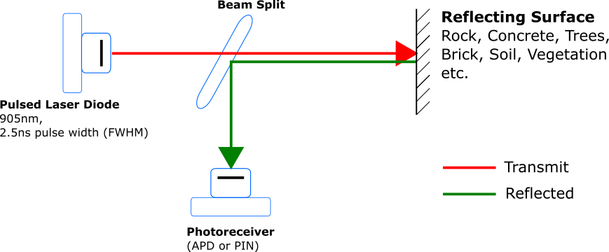
Good afternoon all, I have been racking my 'optics novice' brain on how to use the same optical path for both the transmit and receive optics for a simple laser range finder. For simplicity in the diagram below I have removed the collimation asphere, and beam expanders that I use to get the divergence under control.
To achieve that shown in the diagram I thought I could take advantage of the fact that the laser diode is predominantly polarised in the plane parallel to the laser diode emitting surface. Pass it through a polarised cube beam splitter, through a quarter wave retarder to circularly polarise the light. Then when it is reflected it would pass through the retarder again, after which it would be 90deg to the original and therefore would hit the polarised cube beam splitter and be passed out at in the manner shown below.
But... It dawned on me that it was very likely that the polarisation would not be maintained upon reflection from real world surfaces, and at varying angles of incidence. After a bit more reading I found that the polarisation after reflection would be random. This kind of ruined my idea.
So my question is, how can I achieve the scenario above, can it be done with a basic plate beam splitter. Ideally, I would like as much of the transmit light to hit the reflection surface, but if a small amount was deflected I could actually use that light for a timing trigger. I would also like as much of the reflected light to hit the APD but again the power level of this light would be so small that I don't think it would hurt the laser diode too much if a fraction went back to the laser diode.
Can anyone give me a pointer to where I should direct further reading and experimentation?
thank you

