While charging a capacitor by a DC source, half energy is wasted as heat. Can't we save that energy? Here I am talking about $$(1/2)CV^2 $$ which is wasted while supplying $$CV^2$$
-
$\begingroup$ It's only wasted if you do it poorly. If you use an inductor and a good switch one can pretty easily reach about 97-98% efficiency. That's how your switching power supplies do it. $\endgroup$– CuriousOneCommented Jan 28, 2016 at 9:09
-
$\begingroup$ @CuriousOne : Is switching power supply like a forward biased diode in series. $\endgroup$– Anubhav GoelCommented Feb 8, 2016 at 9:51
-
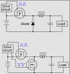
1$\begingroup$ A switching power supply is a circuit that stores electrical energy in an inductor, which it then transfers into a capacitor. This can be repeated periodically without significant losses with at least two switches, one of which can be a diode: learningelectronics.net/images/quiz/02480x01.png. After connecting an inductor to a voltage source, the current becomes a linear function of time with $L{dI \over {dt}}=U$. After disconnecting the inductor from the power source the diode starts conducting and the energy stored in the inductor keeps charging the capacitor without loss. $\endgroup$– CuriousOneCommented Feb 8, 2016 at 10:47
-
$\begingroup$ Possible duplicates: physics.stackexchange.com/q/187774/50583, physics.stackexchange.com/a/202150/50583 and their linked questions. $\endgroup$– ACuriousMind ♦Commented Aug 28, 2018 at 20:49
-
$\begingroup$ @ACuriousMind Not duplicates but related. $\endgroup$– Anubhav GoelCommented Aug 29, 2018 at 1:32
1 Answer
As has been pointed out by @CuriousOne you can save the energy but let's me first explain the context in which one usually first meet this loss of energy.
A capacitor $C$ in series with a resistor $R$ and a voltage source $V$ is charged.
If the final charge on the capacitor is $Q$ then the work done by the voltage source is $VQ$ and as $Q=CV$ the work done by the source is $CV^2$.
The energy stored in the capacitor is $\int_0^QVdQ = \int_0^Q\frac Q C dQ = \frac 1 2 CV^2$. The integration has to be done because as the capacitor is charged the voltage across its plates changes.
The missing energy is $\frac 12 CV^2$ and that is lost as heat in the resistor.
To show that is true and the loss is independent of the value of the resistance in the circuit one must do a bit more circuit analysis.
During the charging process it can be shown that the current in the circuit $I(t) = \frac V R e^{-\frac {t}{RC}}$.
The power dissipated in a resistor is $I^2R$ so during the changing process the energy dissipated in the resistor is $\int_0 ^\infty \frac {V^2}{R^2} e^{-\frac {2t}{RC}} dt = \frac 1 2 CV^2$.
If the capacitor is charged in the way described changing the resistance value will not change the amount of energy lost as heat.
If the resistance in becomes very low instead of the charging process following an exponential curve the current in the circuit becomes a damped sinusoid and then energy is lost as heat and electromagnetic waves because the electrons in the wires are accelerating and unbound accelerating charges emit electromagnetic radiation.
The factor $\frac 1 2$ comes into play in lots of other situations eg the energy stored in an inductor $\frac 1 2 LI^2$ and in a spring $\frac 1 2 k x^2$.
In all these cases the "missing" energy turns up as heat due to the resistance in an electrical circuit and friction in the mechanical example.
Using Hooke’s law for a spring of spring constant $k$ which has a static extension of $x$ when a weight $mg$ is hung from its end $mg= kx$.
The work done by the gravitational force is $mgx = kx^2$ whereas the energy stored in the spring is $\frac 12 k x^2$
In this case imagine releasing the mass when the spring is unextended.
What would happen?
The mass would oscillate about the static extension position and as frictional forces converted mechanical energy into heat the mass would eventually reach the static extension position.
So how can you save that missing energy?
One reason for introducing the spring is that perhaps discussing the motion of a spring-mass system makes it easier to understand an answer to this question?
What you do is, with the spring unextended, release the mass and catch hold of the mass when it first stops after half a period.
If there are no frictional forces this will happen when the extension of the spring is $2x$.
The work done by the gravitational force is now $mg 2x = 2kx^2$.
The energy stored in the spring is $\frac 1 2 k (2x)^2 = 2 k x^2$ which is exactly equal to the work done by the gravitational force.
No energy wasted as heat.
So what about the capacitor?
Here you need as small a resistance value in the circuit as possible so that the voltage across the capacitor oscillates between $0V$ and $2V$ about $V$ (the final voltage value), just like the spring.
In this case you disconnect the capacitor from the voltage source after half a period when the voltage across the capacitor is 2V.
The work done by the voltage source is now $V 2Q = 2CV^2$.
The energy stored in the capacitor is $\frac 1 2 C (2V)^2 = 2 CV^2$ which is exactly equal to the work done by the voltage source.
No energy wasted as heat.
You have all the energy supplied by the voltage source stored in the capacitor.
Update requested by @user54826
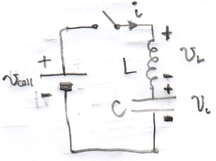
To carry on the spring mass analogy, you need to add an inductor to the electrical circuit.
So you need a circuit with a capacitor which stores energy in an electric field (potential energy) and an inductor which stores energy in a magnetic field ("kinetic energy") as explained here.
Initially the current is zero and the charge on the capacitor is zero.
The switch is closed and although the current is zero the current is changing with the inductor producing an emf $L\frac {di}{dt}$ in opposition to the change.
When current starts to flow the capacitor starts to charge and develop a potential difference across it $\frac q C$.
Allying Kirchhoff's voltage rule for the circuit gives
$$L \frac {di}{dt} + \frac q C = V_{\rm cell} \Rightarrow L\ddot q + \frac 1 C q = v_{\rm cell} $$
The capacitor continues charging but when the potential difference across the capacitor is $v_{\rm cell}$ there is still a current in the circuit (ie the inductor has a store of energy in its magnetic field) and as the current cannot stop instantaneously the capacitor continues to charge until the voltage across it reaches $2v_{\rm cell}$ when the current becomes zero.
It is at this point that if you opened the switch all the energy delivered by the cell is now stored in the electric field of the capacitor.
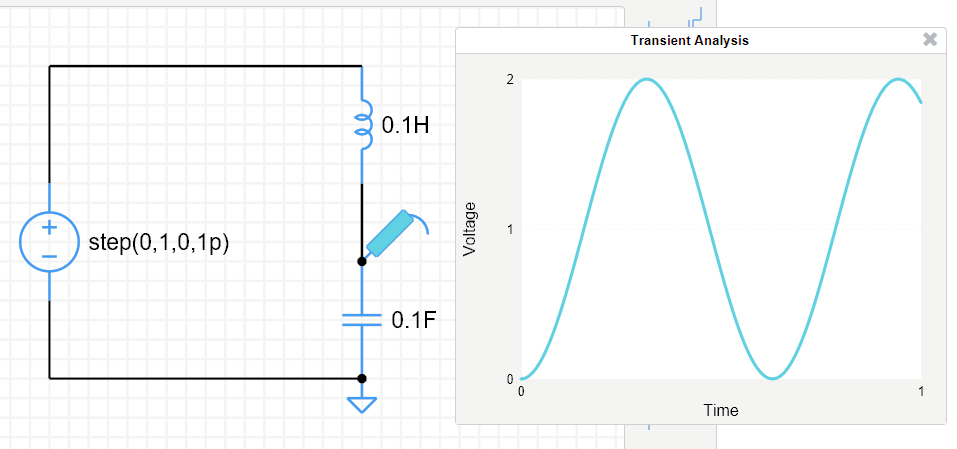
Carrying on there would be an oscillation of the voltage across capacitor between $0$ and $2v_{\rm cell}$ about a voltage of $v_{\rm cell}$ as shown in the output of a simulation with the cell voltage being $1\,\rm V$. Please note that this simulation did not work for me when using Firefox under Windows 10 but did work with Edge.
The period of the oscillation is $2\pi\sqrt{LC}$.
In a comment made by @CuriousOne there is a link to the following images but no explanation.
These are in fact examples of switched mode power supplies.
There is more information and some nice animations about the buck convertor and the buck-boost converter here.
Update 2: As requested in the discussion below this answer, here are some more information and clarifications:
Electromagnetic radiation is always emitted but usually the energy loss due to this process is much less that via other processes - heating. In effect when all else fails lose energy by emitting electromagnetic radiation.
If we assume that one has normal conductors (with resistance) and inductance (even parasitic) then those oscillations shown in the transient graph would reduce in amplitude as time went on. As the resistance becomes smaller the electromagnetic radiation loss would become more significant as compared with the ohmic heating loss.
-
$\begingroup$ Before I award the bounty, could you please give a bit more details for the last part of your answer? I am interested to know how come the voltage will oscillate between 0V and 2V, and not from 0V to 1V. $\endgroup$ Commented Aug 29, 2018 at 7:49
-
$\begingroup$ @user54826 I have updated my answer. $\endgroup$– FarcherCommented Aug 29, 2018 at 9:41
-
$\begingroup$ Extremely nice, bounty deserving answer so far. Thanks for the inductance details! But now I have a problem understanding why in the case of no inductance, some energy will be lost as EM radiation whilst in the RLC case, not necessarily, despite the fact that the current is time-varying. $\endgroup$ Commented Aug 29, 2018 at 10:21
-
$\begingroup$ @user54826 Just a matter of scale. Electromagnetic radiation is always emitted but usually the energy loss due to this process is much less that via other processes - heating. In effect when all else fails lose energy by emitting electromagnetic radiation. $\endgroup$– FarcherCommented Aug 29, 2018 at 10:35
-
1$\begingroup$ Assume that you have normal conductors (with resistance) and inductance (even parasitic) then those oscillations shown in the transient graph would reduce in amplitude as time went on. As the resistance becomes smaller the electromagnetic radiation loss would become more significant as compared with the ohmic heating loss. $\endgroup$– FarcherCommented Aug 29, 2018 at 12:39


