2
$\begingroup$

Five choices I made up:

a.
enter image description here

b.

enter image description here

c.

enter image description here

d.

enter image description here

e.

enter image description here

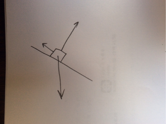
One thing I know immediately is that the vectors have to cancel each other at last so there is no net force acting on it.

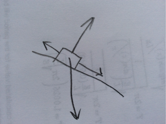
a. certainly qualifies.

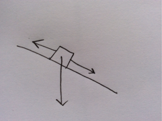
b. doesn't. If the components of the vertical arrow leave the object sliding down the incline.

c. has two vector forces directed down the incline, but only of which is is cancelled.

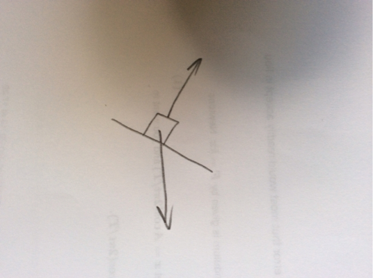
d. is tricky.

There is a unbalanced force going into the plane. But that vector won't change the fact that the object is at rest. One would automatically realized there is a normal force preventing the object from falling into the plane.

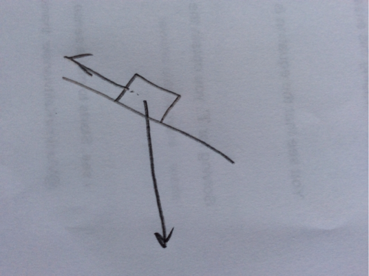
e is basically the same as c, except that the normal force isn't drawn.


If the cause of my confusion still isn't clear to you, it is that I can't settle between choices a and d, due to the lack of the normal force in d.

$\endgroup$

2 Answers 2

2
$\begingroup$

In (d), the net force on the object is into the plane, and so it should be accelerating through the surface of the ramp. Obviously this does not normally occur.

There is a unbalanced force going into the plane. But that vector won't change the fact that the object is at rest.

If there's an unbalanced force on an object, then the object will accelerate in that direction. So if it's at rest, it won't be for long.

One would automatically realized there is a normal force preventing the object from falling into the plane.

If there's a non-negligible force on the object, then you need to draw it in your free-body diagram; the whole point of free-body diagrams is to take a careful inventory of the forces on an object and their directions.

That said, the free-body diagrams for either (a) or (e) could correspond to a box at rest on a ramp, depending on the relative magnitudes of the forces. (In (e), you could imagine pushing lightly on the block sitting on the ramp, but not so much that static friction was overcome.) If we assume that the vectors' magnitudes are roughly correct, though, then (a) is the only reasonable choice.

$\endgroup$
2
  • $\begingroup$ So normal force has to drawn in a free body diagram? $\endgroup$ Commented Aug 19, 2015 at 18:39
  • 1
    $\begingroup$ Yes, sorry if that wasn't clear. See my expanded answer. $\endgroup$ Commented Aug 19, 2015 at 18:40
1
$\begingroup$

$A$ is correct, assuming the forces are the force of gravity $F_g$, the normal force $N$, and the friction force $f$. $D$ is not ideal because you should draw $N$ in this case.

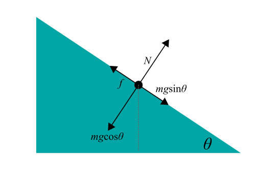
You might be confusing yourself about $E$ because you are drawing $F_g$ as well as the component of $F_g$ in the direction parallel to the plane ($mg\sin\theta$).

One thing you can do is decompose $F_g$ into components that are parallel and perpendicular to the plane—as long as the component vectors sum to the original $F_g$ vector (indicated by the dashed line in the following diagram).

Then, since the object is not sliding along the plane or "rising" or "falling through" it, you know that both the sum of the forces parallel to the plane and the sum of the forces perpendicular to the plane must be zero.

If you make this correction to $E$, you have basically found a FBD equivalent to $A$.

enter image description here

$\endgroup$

Your Answer

By clicking “Post Your Answer”, you agree to our terms of service and acknowledge you have read our privacy policy.

Not the answer you're looking for? Browse other questions tagged or ask your own question.