2
$\begingroup$

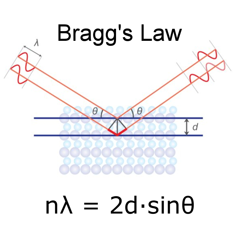
This is the popular diagram surrounding the Bragg's law for X ray diffraction:

enter image description here

But what I seem to not be able to understand is when they say that the reflected waves interact constructively to create peaks. I dont see how the two reflected rays can superimpose at all because they dont share the same path. They seem to be separate and far from each other, so how can they interfere constructively or destructively ? Or is the detector just receiving individual waves and merely considering a high intensity if all of those waves are in the same phase ?

It seems to me that these two reflected waves can never "fully" superimpose on each other at least not in the reflected direction owing to the fact that after reflection the waves are rather spherical and not planar.

$\endgroup$
3
  • $\begingroup$ The directed lines represent waves (e.g., plane waves or spherical waves). The extent of the waves is larger than the extent of the lines. That is, they do not only exist right on top the lines, but rather those lines just indicate the direction of travel of the wave. The point is that one wave reflects off of one atom (or sheet of atoms) and another reflects of another atoms (or sheet of atoms) and those reflected waves have a phase difference related to the locations of the atoms. $\endgroup$
    – hft
    Commented Sep 13, 2022 at 19:34
  • $\begingroup$ @hft okay but where exactly does that phase difference result in a constructive or destructive interference ? For example, i could choose a point such that both the reflected waves are in sync despite the initial phase difference. Similarly i can find where they cancel each other. I can find such points for every angle of incidence. But then what makes the Bragg angle where a peak is observed special ? And what is the "peak" really ? $\endgroup$ Commented Sep 13, 2022 at 19:42
  • $\begingroup$ "i could choose a point such that both the reflected waves are in sync despite the initial phase difference. " No you can't because you don't get to meaningfully adjust the distance to the detector. That detector distance is simply a very large distance compared to the atomic spacing. As you see, nothing in the equation depends on the distance to the detector. $\endgroup$
    – hft
    Commented Sep 13, 2022 at 19:46

1 Answer 1

2
$\begingroup$

The lines in the diagram represent the direction of travel of the wave and represent that the waves scatter off of atoms in different locations.

As a preliminary remark, note that the extent of a plane wave is all of space. A plane wave is a function that has a value everywhere, not just along a single line. But, we can draw a line to indicate the direction of the wave vector $\vec k$. The wave is said to be "plane" because it has the same value everywhere along a plane perpendicular to the wave vector.

Note also that the lines in the figure presented in the question are drawn in a way to help illustrate the phase difference. The waves do not literally travel only along the lines. The lines indicate the direction of travel and indicate that the total path length for one of the interfering waves is larger than the other.

Generally, if some atom is at position $\vec R_1$ and for example a plane wave $e^{i\vec k \cdot \vec r}$ reflects off of the atom, the outgoing wave is proportional to: $$ \frac{1}{|\vec r - \vec R_1|}e^{ik|\vec r - \vec R_1|}e^{i\vec k\cdot \vec R_1} $$

If the same incident plane wave reflects off a different atom at a different location $\vec R_2$ the outgoing wave is proportional to: $$ \frac{1}{|\vec r - \vec R_2|}e^{ik|\vec r - \vec R_2|}e^{i\vec k \cdot \vec R_2} $$

There is a phase difference between the waves because the initial plane wave has to travel different distances to get to the different atoms.

In a solid the locations $\vec R_i$ are regularly distributed and cause diffraction patterns. However the expression for the total diffracted wave can be written down for any collection of scatterers at locations $\vec R_i$ as: $$ \sum_i \frac{1}{|\vec r - \vec R_i|}e^{ik|\vec r - \vec R_i|}e^{i\vec k \cdot \vec R_i}\;, $$ where the first factor is the outgoing spherical wave (from each scatterer) and the last factor is due to the incoming plane wave having to travel different distances to each scatterer.

We also use the approximation: $$ |\vec r - \vec R_i| \approx r - \frac{\vec r}{|r|}\cdot\vec R_i\;, $$ in the exponential of the outgoing spherical wave, which we will see is valid when the final observation location $r$ is very large compared to the distance between scatterers.

And we use the approximation: $$ |\vec r - \vec R_i| \approx r\;, $$ in the denominator of the outgoing spherical wave.

For the case of two scatterers we use the above approximation and find the total wave amplitude at the observation point $\vec r$ to be: $$ \frac{e^{ikr}}{r}\left( e^{-ik\hat r\cdot \vec R_1}e^{i\vec k \cdot \vec R_1} + e^{-ik\hat r\cdot \vec R_2}e^{i\vec k \cdot \vec R_2} \right) $$

And the total phase difference is: $$ (\vec k - k\hat r)\cdot(\vec R_1 - \vec R_2) = \frac{2\pi}{\lambda}2d\sin(\theta) $$

$\endgroup$
2
  • $\begingroup$ when a beam falls on an individual atom, isnt the X ray scattered in all directions ? $\endgroup$ Commented Sep 13, 2022 at 20:12
  • $\begingroup$ Yes, that is seen in the spherical wave factor $e^{ikr}/r$. Independent of direction. Dependent only on the magnitude of the distance. $\endgroup$
    – hft
    Commented Sep 13, 2022 at 20:14

Your Answer

By clicking “Post Your Answer”, you agree to our terms of service and acknowledge you have read our privacy policy.

Not the answer you're looking for? Browse other questions tagged or ask your own question.