7
$\begingroup$

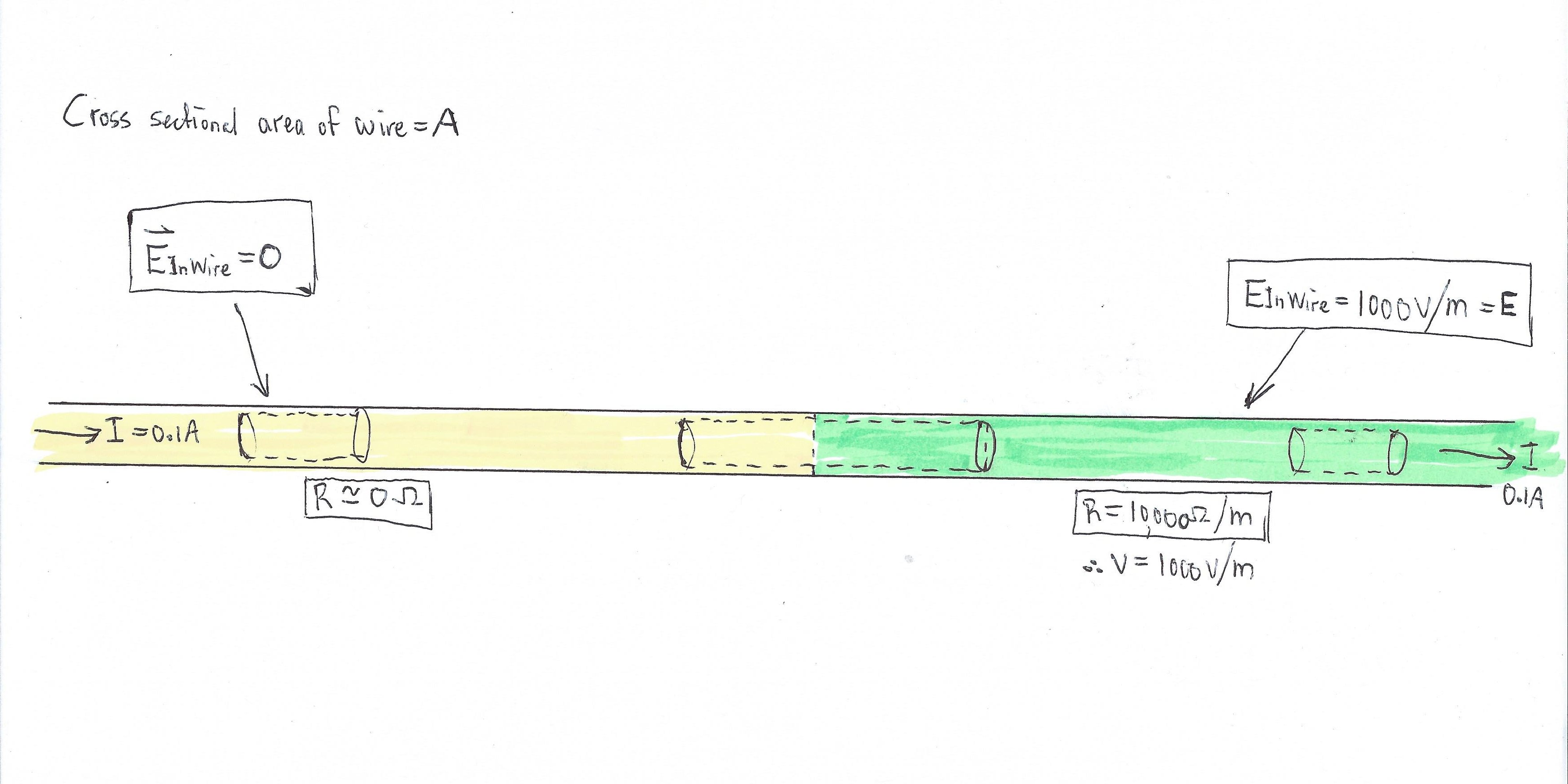
Consider the very long, current-carrying wire in the picture below. On the left-hand side, in yellow, the wire has a very low resistance, that we will consider to be zero. But on the right-hand side in green, the resistance is much higher, for example 10,000 ohms per meter. There is a current of 0.1 A, so in this example the voltage across the resistive part of the wire is 1000 V per meter of wire. The $E$-field inside the resistive part of the wire is therefore 1000 V/m.

Let's do some textbook application of Gauss Law, which states that the surface integral of the electric field, over any closed surface, is equal to the enclosed charge divided by the permittivity constant. On the left, inside the zero-resistance wire, the electric field in the wire is of course zero, because the resistance of the wire is zero, so there is no voltage drop along the wire. As sketched, we take a cylindrical Gaussian surface, just inside the surface of the wire. The electric field is zero everywhere on the Gaussian surface, so the surface integral is zero, and thus there is no enclosed charge. Yes. Everything ship-shape here, noting the well-known fact that there is zero net charge inside a conductor, and that any excess charge resides on the surface, just outside of our Gaussian surface.

Now consider a similar cylindrical Gaussian surface on the right, inside the green resistive wire. The electric field inside the wire here has the value $E$, in this case 1000 V/m. So the product of the electric field and the area is (AE) on each end of the cylinder. However, the electric flux is entering on one end, and leaving at the other end, so the sum of the flux is still zero, telling us there is zero enclosed charge. Gauss wins again.

Now consider the Gaussian cylindrical surface in the center. On the LH end of the cylinder, the flux is zero, because the electric field here is zero. But on the RH end the flux is (EA), the non-zero electric field strength of 1000 V/m, multiplied by the cross-sectional area of the wire. Hmmm. This tells us that there must be charge enclosed inside the wire, inside of the cylindrical Gaussian surface. But it is well known and accepted that there is no charge inside of a conductor, and so we have an apparent paradox, a violation of the Gauss Law.

I'm pretty sure that I know what is happening, but it is such a cute problem that I would not wish to deprive others the opportunity to think about it.

enter image description here

$\endgroup$
1
  • $\begingroup$ I believe this same problem (but with two arbitrary unequal resistances) is somewhere in Purcell & Morin. $\endgroup$ Commented Aug 28, 2022 at 23:30

5 Answers 5

24
$\begingroup$

As far as I can see, there is nothing wrong here: Since the properties of the material change where the green and the yellow parts meet, you do not have a single conductor but two different ones with a boundary between them. Gauss's law correctly states that there will be a surface charge on that boundary, which is responsible for the discontinuity of the electric field. In particular, as aekmr and J.G. explain in the comments, in a plane where a discontinuous change in the conductivity $\sigma(\vec r)$ occurs and through which the (homogeneous) current density $\vec j$ flows, the electric field will change (also discontinouosly) so that $\sigma(\vec r) \vec E(\vec r) = \vec j$ remains constant for all $\vec r$.

Remark:

The formula $\sigma \vec E = \vec j$ is simply Ohm's law, formulated locally. If there is a current density $\vec j$ through a volume $lA$ of length $l$ above an area $A$, which is driven by the constant electrical field $\vec E$, the current is $$ I = \int_F \vec j \underbrace{d\vec f}_{\perp F} \overset{\sigma \vec E = \vec j}= \sigma \int_F \underbrace{\vec E}_{\text{constant}} d\vec f = \sigma \frac{\Delta \phi}{l} \int_F d\vec f = \underbrace{\frac{\sigma F}{l}}_{=1/R} \Delta \phi = \frac{U}{R}~, $$ where $\Delta \phi$ is the change of potential (voltage) $U$ over the length $l$, and $R$ is the global resistance.

$\endgroup$
1
  • 5
    $\begingroup$ Fully agreed with this answer (+1) but maybe it would help OP to state more specifically why their assumption that "there is no charge inside a conductor" is wrong (and in which setting it would be correct): In steady state, the continuity equation implies $\nabla\cdot\vec{j} = 0$ and, if conductivity is constant, this leads to $\nabla\cdot\vec{E} = 0$ and therefore $\rho = 0$. Inhomogeneous conductivity breaks this argument. $\endgroup$
    – aekmr
    Commented Aug 28, 2022 at 18:00
15
$\begingroup$

But it is well known and accepted that there is no charge inside of a conductor

That is where your paradox fails. There will be charge inside the central Gaussian surface, at the interface between the perfect and imperfect conductors.

Electric field lines must begin and end on charges. At the interface the electric field abruptly changes from zero to 1000 V/m. There must be a surface charge density (equivalent to $\epsilon_0 E$ and in accordance with Gauss's law) on the interface between the perfect and imperfect conductor where the electric field lines begin.

$\endgroup$
1
$\begingroup$

When I posted this question, I smugly claimed that I was pretty sure what was going on. My conclusion was the same as contributor "basics", that there had to be a radial component of the field at the cylinder wall, so that the electric flux entering the cylinder wall was equal to the flux leaving the end of the cylinder at the RH side, in the resistive material. However, on further thought, I just can't see how electric field lines can be sketched to make this hypothesis workable. If "basics" can provide a sketch of how the field lines would actually look, then I should like to see it.

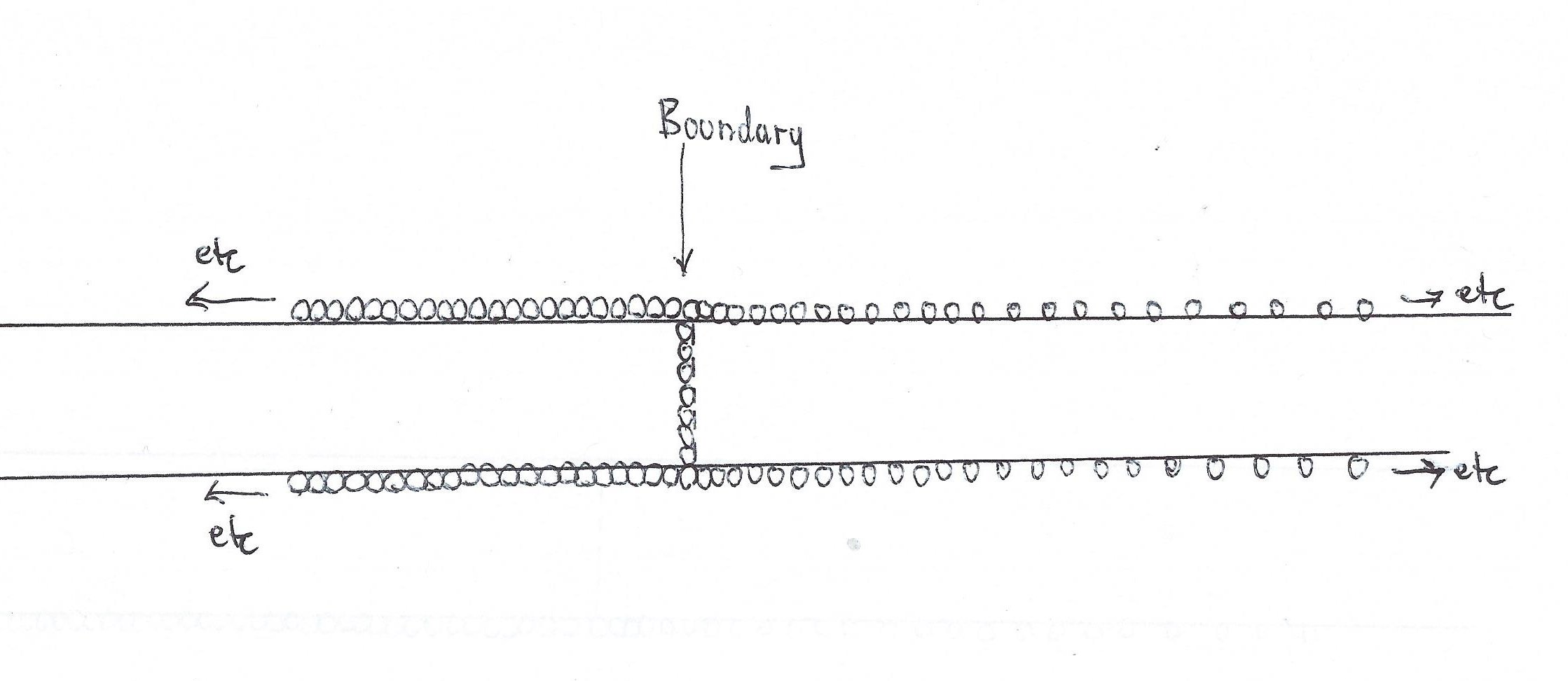
I am therefore convinced of the explanation given by others, that there must be charge at the boundary between the low and high resistivity materials. This keeps Gauss Law happy, and makes it possible for the Efield to be discontinuous at the boundary. I have attached a sketch showing very roughly how the charge distribution would look like at the boundary and at the surface of the wires, to provide essentially zero field to the left of the boundary, and a uniform electric field E to the right of the boundary, as required. The little circles are charges (electrons), and the distance between them indicates the charge density. I don't claim that the surface charge density is exactly uniform where I have shown the circles as touching, but you get the broad idea.

Therefore the common statement that the charge inside a conductor is zero is not true when the conductor carries a current, and the resistivity of the material is not constant. Also, if the resistivity changes progressively along the length of the current-carrying conductor, there will be excess charge within and throughout the conductor that is not on any surface as such, so the common statement that all the charge resides on the surface is not true in this case.

enter image description here

$\endgroup$
1
  • $\begingroup$ As it’s currently written, your answer is unclear. Please edit to add additional details that will help others understand how this addresses the question asked. You can find more information on how to write good answers in the help center. $\endgroup$
    – Community Bot
    Commented Aug 29, 2022 at 8:10
0
$\begingroup$

There are already good answers to your question. I think you were trying to fail Gauss's law. To do so, you must use a pathological surface or volume where surface or volume integral are impossible to calculate. The surface integral and flux become problematic in two cases:

  • There is no bijective parametrization of the surface and you cannot calculate the flux integral.
  • The surface is not orientable. You can neither define a volume enclosed by the surface nor decide if the flux is positive or negative. A Moebius strip is not orientable, how do you evaluate the direction of the induced e.m.f when the strip is positioned in a time varying magnetic field? https://mathoverflow.net/questions/51169/flux-through-a-mobius-strip

The same goes in 3D. Klein's bottle has no interior nor exterior and you cannot evaluate the enclosed charge? i.e. Gauss's law fails.

I personally favor Maxwell's equations because they are strictly local and do not care about surface orientation. But to be fair, if the field sources are localized on a fractal surface you cannot calculate curl, gradient and divergence as usual and need an extension of the classical definition of these operators.

$\endgroup$
2
  • $\begingroup$ Not sure if there this answer applies to the problem stated, but upvoted because the Moebius resistor page link led me to the Ayrton–Perry winding wiki page and both ways to minimize parasitic inductances are interesting. $\endgroup$
    – UVphoton
    Commented Aug 30, 2022 at 12:20
  • $\begingroup$ @UVphoton - You may be interested in a question that I posted today re Moebius resistors. $\endgroup$
    – Truth
    Commented Sep 1, 2022 at 3:35
-4
$\begingroup$

Basically u can't say it as a whole conductor.It is joining of 2 conductors whom both have different properties regarding gauss law. And you will be right if you take it as a separate. Thanks

$\endgroup$
1
  • 3
    $\begingroup$ As it’s currently written, your answer is unclear. Please edit to add additional details that will help others understand how this addresses the question asked. You can find more information on how to write good answers in the help center. $\endgroup$
    – Community Bot
    Commented Aug 29, 2022 at 10:43

Your Answer

By clicking “Post Your Answer”, you agree to our terms of service and acknowledge you have read our privacy policy.

Not the answer you're looking for? Browse other questions tagged or ask your own question.