2
$\begingroup$

enter image description here

According to the definition of the dielectric constant(k) for a dielectric, the electric field in the dielectric is defined as the corresponding electric field in vacuum divided by k.

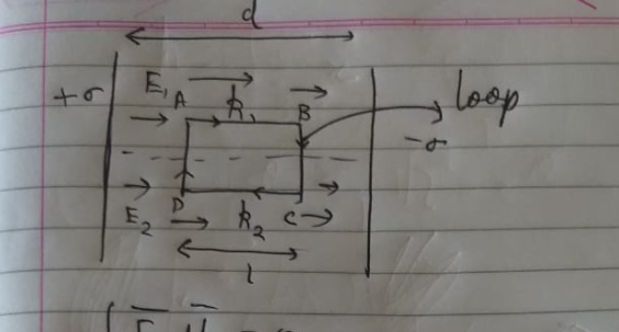
We are also aware that the cyclic line integral of a electrostatic conservative field is 0 in a closed-loop. Keeping this in mind, let us consider three dielectric slabs of dielectric constants k1 and k2. The parallel plate metal capacitor is made of infinite plates with a uniform area and a distance "d" between its plates. I took a loop (as shown in my figure below ) and proved that the fields in the two slabs are equal. However, we know from the definition of a dielectric constant (and as shown in Concepts of Physics by Dr. H.C. Verma) that the electric field in a dielectric is 1/k times the field in vacuum. I have hence reached a seeming contradiction.

enter image description here

$$ \oint \vec{E} \cdot dl = 0$$

$$ \implies \vec{E_1} = \vec{E_2}$$

But by definition $\frac{E_o}{k_1} =\frac{E_o}{k_2}$

Combining equations $\frac{1}{k_1} = \frac1{k_2}$

... which seems to be a contradiction?

My attempt at resolving this

I believe that the E_o (which is the electric field in vacuum of the capacitor ) cannot be taken as the same for both dielectrics. This is because on inserting the dielectric slabs, there would be an additional polarized charge on the interface of the dielectric (which now coincides with the metal plate surface according to my setup). The metal plate however wants a 0 electric field inside it hence it would redistribute its charge in a way to achieve this. Since this charge has redistributed, the field in the region where k1 is to be inserted i.e. E_o is not the same (as it changes due to the deposition of charge from one of the sides of the dielectric)

Problems with my Theory:

  1. There is no rigorous mathematical proof and I am not convinced of my physical argument as it seems to have a very low degree of rigor.

  2. When we defined E_in dielectric = {E_(in vacuum)/k} I believe we defined E_o as the field in vacuum disregarding any effects of the dielectric (I think there is a direct contradiction here and this may be entirely wrong and we may have to in fact consider the effect if any brought about by the insertion of a dielectric.)

  3. Fringe fields of the capacitor may be interfering here somehow (although i only took a loop very close to the interface)

$\endgroup$

1 Answer 1

1
$\begingroup$

Both the electric fields are equal

The net electric fields inside both the dielectrics need to be same. Why? Because since electric fields are conservative, which means we can define a corresponding electric potential and thus electric potential difference. The electric potential difference between any two points, $a$ and $b$, is

$$\Delta V=\int_a^b \mathbf E \cdot \mathrm d \mathbf l$$

The value of this potential difference stays the same irrespective of the path taken in going from $a$ to $b$.

Now, since both the plates are conductors, thus the potential of every point on a certain plate is same. This also implies that the potential difference between any two points, one on the left plate and another on the right plate, is the same. So, now let's find the potential difference between two points which have the dielectric 1 separating them. That would be

$$\Delta V_1 = \int _0^d \mathbf E_1 \cdot \mathrm d \mathbf x=E_1d$$

Similarly, the potential difference between any two points separated by dielectric 2 will be

$$\Delta V_2 =\int _0^d \mathbf E_2 \cdot \mathrm d \mathbf x=E_2d$$

But since $\Delta V_1=\Delta V_2$, therefore

$$E_1d=E_2d\implies E_1=E_2$$

This also implies that

$$\oint \mathbf E\cdot \mathrm d \mathbf l=0\tag{1}$$

for any loop in between the two plates. This can also equivalently expressed by the following Maxwell's relation

$$\nabla \times \mathbf E=-\frac{\partial \mathbf B}{\partial t}\tag{2}$$

Since $\displaystyle\frac{\partial \mathbf B}{\partial t}$ in the case of electrostatic field only, thus the equation $(2)$ simplifies to

$$\nabla \times \mathbf E=0\tag{3}$$

Do note that in the above analysis, I have ignored the fringing of field lines, because it is irrelevant to the core question. Even if we include fringing of field lines, still the equations $(1)$, $(2)$ and $(3)$ will hold true.

But how is this consistent with the definition of a dielectric constant?

This is perfectly consistent with the definition of dielectric constant. The reason why we encounter this paradox is because of our fallacy in assuming that the external field (in other words, the field due to free charges) in both the dielectrics is the same, whereas it's not. The charge density on the conducting plates abruptly changes at the level of the dielectric interface. Thus the surface charge density of the conducting plates is not uniform and, thus, neither is the external electric field. Moreover, external electric fields are related by the relation

$$\frac{E_{\text{ext}/1}}{k_1}=\frac{E_{\text{ext}/2}}{k_2}$$

This relation is derived from the fact that the net field should be the same in both the dielectrics, as I discussed above.

$\endgroup$
4
  • $\begingroup$ I am afraid the contradiction pertaining to the definition of field in dielectric (which implies that k1=k2) wasn't answered $\endgroup$ Commented Jun 9, 2020 at 13:34
  • $\begingroup$ @SchwarzKugelblitz I have updated the answer, please take a look. $\endgroup$
    – user258881
    Commented Jun 9, 2020 at 13:42
  • $\begingroup$ Basically you agree with my theory? $\endgroup$ Commented Jun 9, 2020 at 14:10
  • $\begingroup$ @SchwarzKugelblitz This isn't your theory, this is just classical electrodynamics. You just stumbled upon one of the zillion things that classical electrodynamics predicts. $\endgroup$
    – user258881
    Commented Jun 9, 2020 at 14:12

Your Answer

By clicking “Post Your Answer”, you agree to our terms of service and acknowledge you have read our privacy policy.

Not the answer you're looking for? Browse other questions tagged or ask your own question.