3
$\begingroup$

I was solving a textbook exercise which was stated as follows:

Derive an expression for the intensity in the interference pattern for three equally spaced slits. Express in terms of $\delta = 2\pi d \sin(\theta)/\lambda$, where d is the distance between adjacent slits and assume that $D \approx \lambda$.

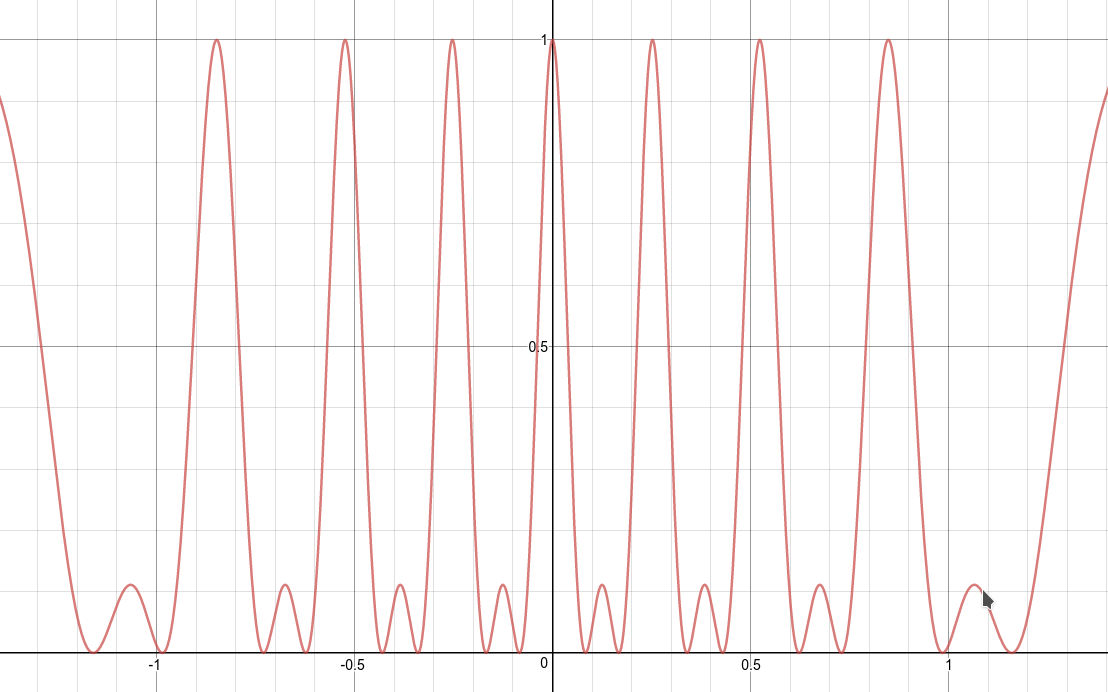
My solution was as follows: $$ I_\theta = \frac{I_0}{9}\bigg(\frac{\sin(\beta/2)}{\beta/2}\bigg)^{2}\big(1+2\cos(\delta)\big)^{2} $$ With $\beta = \frac{2\pi}{\lambda}D\sin\theta$. Which, when plotted, produced a pattern which seemed correct to me:

enter image description here

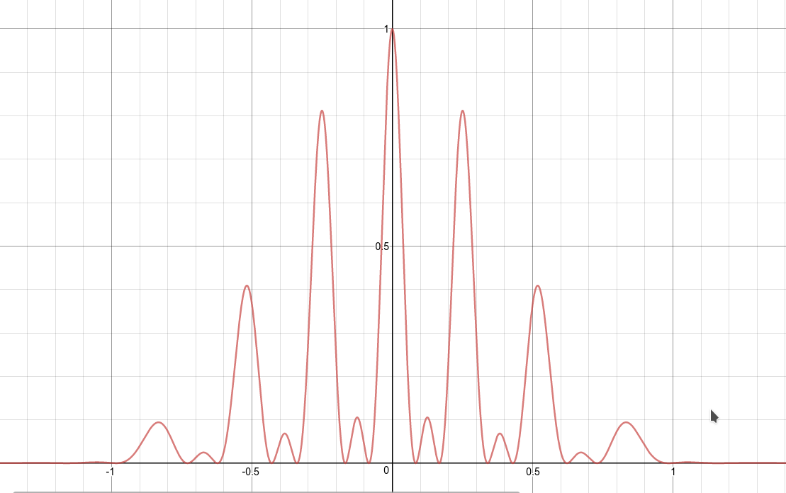
When, however, I checked the textbook results, they argumented that since $D \approx \lambda$, they could ignore diffraction effects, so one needed only to consider interference effects. Their solution was as follows: $$ I_\theta = \frac{I_0}{9}\big(1+2\cos(\delta)\big)^{2} $$ Which simply omits the diffraction factor. This, when plotted, looks like:

enter image description here

Which, to me, seems incorrect.

Was diffraction simply left out because it didn't matter to the exercise, or is it true that diffraction effects can be ignored when $D \approx \lambda$? And if so, why?

$\endgroup$
1
  • $\begingroup$ a waveguide whose dimension is $\lambda$ and ends abruptly does diffract strongly, same with a screen with a hole of that size. $\endgroup$
    – hyportnex
    Commented Jun 3, 2017 at 17:14

2 Answers 2

1
$\begingroup$

As always, whether it's "safe" to ignore some effect depends on what you are trying to do. If your experimental question is about the spacing between the bright maxima or the relative intensities of the bright and dim maxima, your two curves agree. If your experimental question is about the relative intensities of the bright maxima, including the fundamental question of how many bright maxima you should expect to see, the two curves are different. Deciding what's important in an experiment is a judgement call. However, if I were setting up an experiment expecting the second pattern and saw the first instead, I would wonder what was missing from my prediction.

In general it's "safe" to ignore diffraction when the relevant wavelength is very short, $D \gg \lambda$; it's possible the book simply contains a typo.


I'm a little perturbed at the difference between my answer ("it's safe to ignore diffraction only if $D\gg\lambda$"), which is correct in my experience, and the correct statement currently in the other answer ("when $D\approx\lambda$ then the first diffraction minimum is at $\pi/2$ radians"). And I think it comes down again to the question of just what is meant by "ignore."

Usually when we talk about ignoring diffraction, we mean that we can pretend that light is not a wave. That means, mainly, that if well-collimated light is sent through some aperture, the image that's displayed has the same shape as the aperture does. In order for this to take place, the first (and subsequent) diffraction minima must be at small angles, not at large angles. As the aperture gets smaller, diffraction causes the transmitted light to spread out more and more. Once you get to $D\approx\lambda$, diffraction has basically destroyed all the information about the shape of the aperture: it is diffraction which causes light from the aperture to be emitted at angles up to and including $\pi/2$ radians.

However, for combining single-slit diffraction with multiple-slit interference, the multiple-slit pattern is simpler if the individual slits are very narrow, so that single-slit diffraction smears the double-slit pattern over a wider area. So in this case, "ignoring single-slit diffraction" is consistent with making the assumption $d \gg D$, so that the small-angle diffraction details are explained by the slit separation $d$ without confounding due to the slit widths $D$. (If there are very many slits, as in a diffraction grating, this constraint becomes less important.)

An aside: I haven't made the effort to remember where the $\sin(\sin\theta)$ structure comes from in your expressions, but I more-or-less reproduce your plots with $d=3.9\lambda$, $D=0.3\lambda$.

$\endgroup$
1
  • $\begingroup$ Your updated answer makes it all very clear. Thank you. My plot values, if I'm not mistaken, were $d = 8\lambda$ and $D = \lambda$. $\endgroup$ Commented Jun 5, 2017 at 19:22
0
$\begingroup$

The effects of diffraction can indeed be ignored if $D \approx \lambda$. The angle $\theta$ at which the first minimum due to diffraction appears, is given by: $$ \sin\theta = \frac{\lambda}{D} $$ So if $D \approx \lambda$, then $\sin \theta = 1$, so $\theta = \pi/2$. Which means that the first minimum in intensity to appear on the screen is found for $y=\infty$. Therefore, the intensity in the maxima created by interference shall be equal to the intensity in adjacent maxima.

I hope this clears things up.

$\endgroup$
2
  • $\begingroup$ This is not consistent with the figures you have produced, where the diffraction term $\sinc^2(\beta/2)$ produces an intensity minimum near one radian (assuming I am reading your plots correctly). $\endgroup$
    – rob
    Commented Jun 3, 2017 at 16:37
  • $\begingroup$ @rob♦ The plots are intensity ($I$) against the angle of diffraction ($\theta$). I believe that the intensity should converge towards a minimum in $\pi/2$, in which case no real minima are produced due to diffraction. A minimum shall be achieved in $\pi/2$ and no angles larger than that are possible. I think the textbook was (like you suggested) aiming to illustrate the spacing between the relative maxima. $\endgroup$ Commented Jun 4, 2017 at 14:53

Your Answer

By clicking “Post Your Answer”, you agree to our terms of service and acknowledge you have read our privacy policy.

Not the answer you're looking for? Browse other questions tagged or ask your own question.