4
$\begingroup$

I wonder how I can model anodized aluminium reflectivity in ray tracing-based optical simulation. I know that the parts my company is using are anodized to get covered with a ~20 um (as specified) thick corundum layer. I would like to be able to properly model angular dependence of such a surface reflectivity. I am using Zemax, but please do not limit yourself to it. Any hint is welcome.

The two options I can think of are 1) Create a model coating in Zemax by specifying reflectivity vs. angle. Can be done if I know the values. I could not find them so far. Could be measured as well but that's a major effort which I'd like to spare. 2) Specify a thin layer of corundum on top of a bulk aluminium part in Zemax. However I could not find the dispersion data for Al2O3 at 10.6 um and I cannot find anything in Zemax' material catalogues. Besides, I assume such a layer of 20 um thickness would act as a thin film resulting in AR or HR properties. But I don't think the anodization process is precise enough in terms of layer thickness so that I can rely on this side effect.

Any help or comment is highly appreciated.

$\endgroup$

2 Answers 2

2
$\begingroup$

In the optics community we usually refer to $\text{Al}_2\text{O}_3$ as sapphire instead of corundum which is the geologists name for it. However, when we talk about sapphire in optics we are usually referring to the crystalline form, and I'm not sure if your $20\ \mu\text{m}$ coating will be crystalline or not. Another difficulty lies in the fact that the optical properties of sapphire can change dramatically with small amounts of doping which is why the gemstones can be found in all sorts of different colors

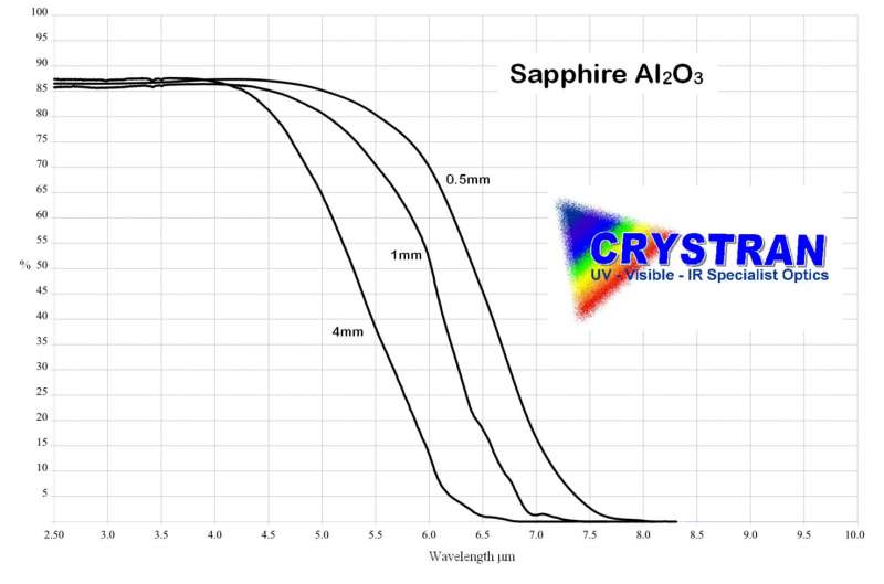
Unfortunately, I was unable to find a lot of data on Sapphire at $10.6\ \mu\text{m}$. All of the plots I could find (such as the one below) show that the tranmissivity at that wavelength is very low. Unfortunately, the losses of many optical material at such long wavelengths can be very high. I know that in fused silica the absorption coefficient is around 90%. So, the low transmittance doesn't necessarily translate to high reflectance.

enter image description here

*Image From: http://www.crystran.co.uk/optical-materials/sapphire-al2o3

$\endgroup$
4
  • $\begingroup$ Interesting. Thanks for explaining about the name, I was confused by that. I've done some math based on your curves. At 7.5 um, for 0.5 mm thickness, transmission is ~3 %. Then the absorption coefficient is ~7 1/mm, leading to a loss of 25 % for double-pass in a 20 um layer. For λ = 10 um it will be even higher, unless there is a local transmission peak there. Do you agree with this understanding? $\endgroup$
    – texnic
    Commented May 2, 2014 at 15:18
  • $\begingroup$ @texnic Seems pretty reasonable. I don't know where you got the absorption coefficient at 7.5 um though. $\endgroup$ Commented May 2, 2014 at 15:21
  • 1
    $\begingroup$ From your plot. Transmission is 3 %. $I'=I_0\exp(-\alpha t)$, $0.03 = \exp(-\alpha \times 0.5)$, $\alpha = -2\ln(0.03) = 7.01$. $\endgroup$
    – texnic
    Commented May 2, 2014 at 20:12
  • $\begingroup$ I realize now that I did not take surface reflection into account, which is probably responsible for 15 % loss at short wavelengths in your plot: 2 * ((1.75-1)/(1.75+1))^2 = 0.15. But the result (huge absorption at >8 um) stays the same. $\endgroup$
    – texnic
    Commented May 2, 2014 at 20:18
0
$\begingroup$

A typical anodized aluminum part is not going to have very good optical properties.

10.6 um is the wavelength of a CO2 laser. These tend to be powerful lasers - 100 Watt beams are not unusual. But you probably are not using one - you would melt an anodized part.

A typical mirror for these lasers is made from a special grade of OFHC (oxygen free high conductivity) copper. High purity improves electrical conductivity. This improves reflectance and reduces absorption. This is important, as even a small amount of absorption causes heating, thermal expansion, changed mirror shape, and a defocused beam. Also high electrical conductivity corresponds to high thermal conductivity, and better cooling.

To be a mirror, the largest surface irregularities must be much smaller than a wavelength. This is much easier to achieve at 10.6 um than for optical wavelengths. But the mirrors must still be polished. They look like mirrors in visible light. A typical machined Al part will have a diffuse reflection.

A mirror typically does not have a coating. A lens typically has an antireflection coating. A typical lens is made of ZnSe, with an index of refraction = 2.4 at 10.6 um.

The coating is a single layer of Thorium Floride. It is sputtered under high vacuum. The AR coating must 1/4 wavelength thick. It is carefully controlled. Anodized Al is not deposited carefully enough to be an optical coating.

Even with an AR coating, reflectivity is ~1% and absorption ~0.5%. This can cause problems. If a 1 Watt beam reflected beam from a curved surface comes to a focus, it can start a fire.

Dispersion is not a problem for a laser. Dispersion is the change in index of refraction with wavelength.

$\endgroup$
2
  • $\begingroup$ Thanks for the comments. This does not really answer my question though. And yes, I am talking about a laser application: the body of the system is made from aluminium, and since I am talking about a multi-kilowatt laser beam, I need to model radiation load on the Al parts, as well as the amount of reflected light. That's why I am interested in Al2O3-coated aluminium reflectivity. $\endgroup$
    – texnic
    Commented May 4, 2014 at 12:16
  • 1
    $\begingroup$ Yeah, you are right. It has been a long time since I was an optical engineer. Try asking engineers at II-VI, ii-vi.com $\endgroup$
    – mmesser314
    Commented May 6, 2014 at 4:46

Your Answer

By clicking “Post Your Answer”, you agree to our terms of service and acknowledge you have read our privacy policy.

Not the answer you're looking for? Browse other questions tagged or ask your own question.