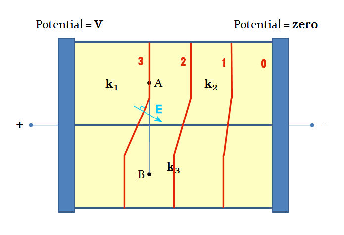
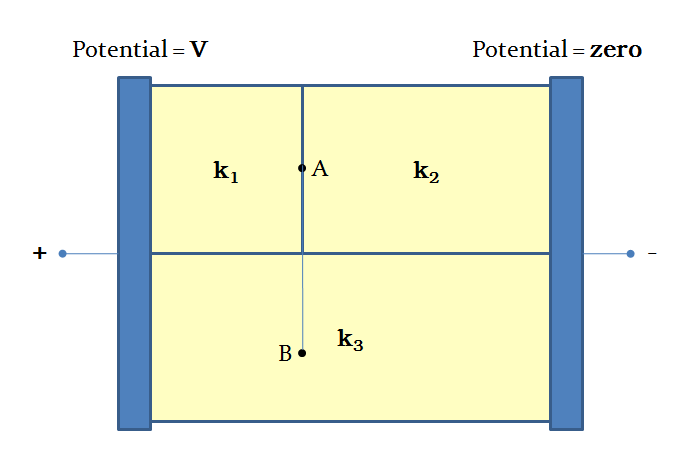
I think the answer is clearer if you consider the equipotential as shown in the diagram below. Forgive their straight line nature as they were easier to draw that way.

Given that $\vec E$ must be perpendicular to an equipotential surface then in your computation of potential difference $\displaystyle V_{AB}=-\int_B^A\vec{E\,}\cdot\mathrm d\vec{r\,}$ the value of $\vec E \cdot d\vec r$ is not zero along the whole path.
Later:
I am sure that the potential and hence the electric field pattern can be computed numerically but as I do not have the facility to do that consideration of a simpler arrangement which might help understand what is going on.
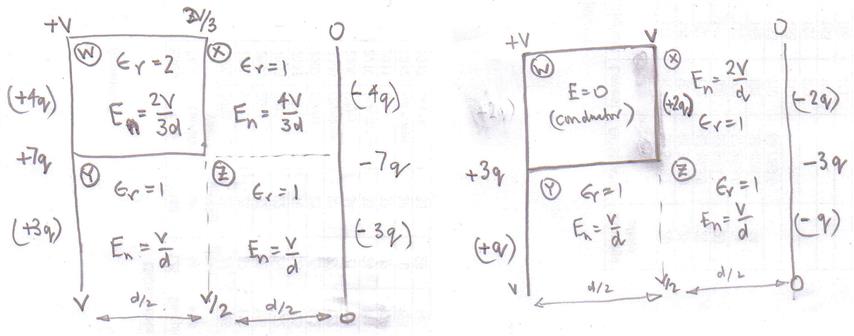
Consider a pair of parallel plates area $2A$, separation $d$ with a potential difference of $V$ between them. Between the plates there is air (relative permittivity $\epsilon_r = 1$) and a dielectric ($\epsilon_r = 2$) of thickness $\frac d 2$ and area $A$ as shown in the diagram left-hand below in which the induced charges on the dielectric are not shown.

The various values shown in the diagram can be obtained by considering the setup as a stand alone capacitor of area $A$, separation $d$ with air between the plates ($Y$ and $Z$) and another stand alone capacitor of area $A$ with a mixed dielectric between the plates ($W$ and $X$).
With the potential difference across the two capacitors $V$ the same then if the charge on the air only capacitor is $3q$ then the charge of the mixed dielectric capacitor is $4q$.
This results in different net electric field $E_n$ within the capacitors.
Now consider what will happen when these two capacitors are combined.
The electric field in region $W$ is less than that in region $Y$ and the electric field in region $X$ is greater than that in region $Z$.
Since in practice there cannot be a discontinuity of the electric field in the air some negative charge $-4q$ must move down the right-hand conducting plate ($0$) with the consequence that the electric field only be perpendicular to the right hand conducting plate at its surface and not inside the body of air.
The induced charges on the dielectric will also move with some of them residing on the bottom horizontal part of the dielectric.
I then thought of another “simple” arrangement where the dielectric in the left-hand diagram is replaced by a conductor to give the situation shown in the right-hand diagram.
Again two capacitors charged so that the potential difference across the plates is $V$ and then joined together.
Again some of the negative charge $-2q$ will move down the right-hand plate and also there will probably a concentration of charge near the corner $Z$ and a deficit of charges around corner $Y$?
So again there will be a distortion of the electric field and the electric field lines would not be perpendicular to the conductors except close to the conductors.
Without a numerical computation other than guessing where the equipotential lines are and drawing the electric field lines at right angles to them that is as far as hand waving goes?


