0
$\begingroup$

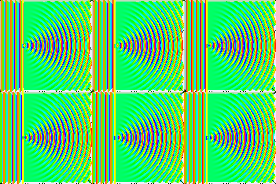
Looking at depictions of waves passing through a slit, I was wondering about the angle of diffraction, for example, for my eyes, the angle created by the line of dark-blue tips below:

enter image description here

I know I may have picked a different threshold to draw the line, but in my readings there seems to be agreement about a certain "maximum" angle, e.g. depending on the wavelength of the waves relative to the slit width.

I was trying to imagine the underlying mechanism of waves for water—which I believe, correct me if I'm wrong, is pressure of matter.

Would a different liquid compound result in a different angle?

Basically I was imagining the "jostling" of water molecules as the pressure front moved along. If the molecules were "stickier" though—I don't know what the correct terminology is—like more "bonded" with one another—then would the pressure front transfer more in all directions (including sideways) than longitudinally forward, effectively widening the angle of diffraction?

When I was trying to search for an answer, I kept coming across articles about "matter-waves," which I think are a different subject.

$\endgroup$
1
  • $\begingroup$ The material properties you're describing are (I think) viscosity and shear waves. Viscosity is usually taken to be negligible when describing waves in a fluid, at least in elementary treatments, but I would assume that someone out there has looked at how non-zero velocity affects things. $\endgroup$ Commented Aug 8 at 15:23

3 Answers 3

1
$\begingroup$

A wave propagates. That is, given the wave now, in a while the wave will have moved forward. There are different ways to calculate where it will go. I won't justify why these ways work.

Rays are one way to predict where it will be next. This is the idea that a wave keeps going in the same direction that it is traveling. Rays are lines perpendicular to the wavefront. Waves propagate perpendicular to their wavefront. This idea often works well. Lens design uses it for very complex lenses. But it is an approximation. At a surface between air and glass, you have to use something else to calculate how much light bends. At a slit, you have to calculate how much light spreads.

Another way to predict where it will be next is to treat every point on the wavefront as a point source of light. The expanding spherical waves add up and interfere. The total is the same as the propagated wave. This works for a slit. You only have point sources in the opening of the slit.

The size of the slit matters. You get different diffraction patterns from slits $1/2$ wavelength wide and $1$ wavelength wide.

Water or any fluid changes the wavelength of light. You can calculate the wavelength from the index of refraction. So the fluid does affect the diffraction pattern.

$\endgroup$
4
  • $\begingroup$ The shape of the slit matters even more. $\endgroup$ Commented Aug 8 at 15:40
  • $\begingroup$ For single slit diffraction of water NO interference is observed, in many poor online water tank videos interference is due to reflections from the sides and other anomalies. Check your 1st year physics text book ... interference with water is only shown for 2 slits, never 1. $\endgroup$ Commented Aug 8 at 16:05
  • $\begingroup$ @PhysicsDave - I am talking about a slightly different thing. Two slits are often treated as two point sources. This is why two slits give an interference pattern and one slit does not. But I am saying if you tread each point of a wave front as a point source, the interference pattern is the propagated wave. This explain why the wave from from a single slit spreads out with no mins and maxes. You could apply it to two slits and get a spread out interference pattern with mins and maxes. $\endgroup$
    – mmesser314
    Commented Aug 8 at 17:57
  • $\begingroup$ yes Huygens was smart at the time (1700s). Also the OP is using the wrong simulation model .... it is based on n number of sources ... where his pattern strongly depends on n. This works for light, Hugens approx = Feynman path integral. $\endgroup$ Commented Aug 8 at 18:22
1
$\begingroup$

Unfortunately your simulation is based on Huygens principle (1700s?) and while brilliant at the time it does not tell the proper story for matter waves. The simulation above is only relevant for light waves.

For single slit diffraction of water NO interference is observed, in many poor online water tank videos interference is due to reflections from the sides and other anomalies. Check your 1st year physics text book ... interference with water is only shown for 2 slits, never 1.

https://esfsciencenew.wordpress.com/2009/03/26/diffraction-wave-spreading-around-an-edge/

https://www.fizzics.org/wp-content/uploads/2019/02/Screenshot-2019-02-02-at-08.59.42.png

$\endgroup$
3
  • $\begingroup$ I see, thank you. To test my understanding, first I reviewed single-slit interference for light—I hope this is still correct. Then I looked for purported single-slit interference in water, e.g. this video—so you are saying the "interference" that seems to appear around 1m30s is actually due to reflections and anomalies, yes? $\endgroup$ Commented Aug 8 at 22:40
  • $\begingroup$ @AndrewCheong yes the video is probably 60 years old and was for 1st year students and prepared by lab technicians. The tank is too small and the time duration is long. $\endgroup$ Commented Aug 9 at 12:42
  • $\begingroup$ @AndrewCheong Huygens was smart at the time (1700s). Your sim is the wrong simulation model .... it is based on n number of sources ... where the pattern strongly depends on n. This works for light, Hugens approx = Feynman path integral. $\endgroup$ Commented Aug 9 at 12:44
1
$\begingroup$

First, note that the properties of the diffracted wave through a slit depends on the wave's spatial wavelength and not on its temporal frequency. Therefore, given the wave's frequency, when comparing different liquid media with air interface, it is sufficient to compare their wavelengths.

The free surface waves of an inviscid fluid satisfies the following dispersion relationship between the frequency $\omega$ and the wavelength $\lambda=\frac{2\pi}{k}$:

$$\omega ^2 = \left(gk+\frac{\sigma}{\rho}k^3\right)\tanh(hk) \tag{1}$$

In Eq. (1) the quantities are defined as: $g$ is the gravitational acceleration and depth $h$, density $\rho$, surface tension $\sigma$ of the fluid, resp.

There are three obvious magnitudes of interest for the surface wavelength at a given frequency.

  1. short wavelengths: $\lambda \ll 2\pi\left(\frac{\sigma}{g\rho}\right)^{\frac{1}{2}}$ and $\omega ^2 \approx \frac{\sigma}{\rho}k^3\tanh(hk)$
  2. intermediate wavelengths: $\lambda \approx 2\pi\left(\frac{\sigma}{g\rho}\right)^{\frac{1}{2}}$ and $\omega ^2 = \left(gk+\frac{\sigma}{\rho}k^3\right)\tanh(hk)$
  3. long wavelengths : $\lambda \gg 2\pi\left(\frac{\sigma}{g\rho}\right)^{\frac{1}{2}}$ and $\omega ^2 \approx gk\tanh(hk)$

For a water - air interface and $\lambda > 7cm$ the first term (gravity) dominates over the second term surface tension (capillary) effect, and this is reversed if the wavelength is $\lambda < 7mm.$

So for long wavelengths the diffraction can be expected to be independent of the fluid material. As it is obvious from Eq (1) the situation is very different in the short wavelength region where surface tension dominates via the surface tension to density factor. In that short wavelength regime the "angle" of diffraction will vary as you change the ratio $\frac{\sigma}{\rho}.$

$\endgroup$

Your Answer

By clicking “Post Your Answer”, you agree to our terms of service and acknowledge you have read our privacy policy.

Not the answer you're looking for? Browse other questions tagged or ask your own question.