0
$\begingroup$

I've had a problem with switches in between parallel circuits.

In this textbook question:Ch.27

The answers state "Note that there is no voltage drop across the voltmeter". However, there is a current across the wire. This goes against what I have been taught - that a flow of charge can only occur in areas of varying voltage.

Also considering this question:
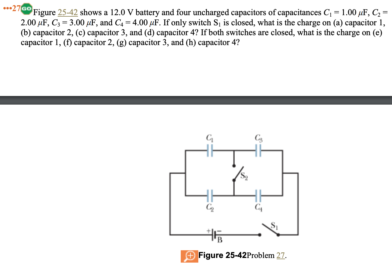
For parts after e), there is also no voltage drop. I suspect that this is due to the nature of capacitors to store charge, thus evening out the voltage, but I am still unsure.

In the latter case, however, the system could be solved by considering two parallel sets of capacitors in series, which allows the flow of electrons. However, in the first, this can only be done to work out the equivalent resistance, but not the final solution (instead requiring the loop rule). Why is this the case?

The rules of whether charge flows seem quite arbitrary and confusing, as in a Wheatstone bridge, there is no current in between, but nor a potential difference. Thus, a clarification would be greatly appreciated.

$\endgroup$
3
  • $\begingroup$ When you say "for parts after e), there is also no voltage drop." do you mean that the answer to parts e, f, g, and h, are all 0 C? Because that's not correct. $\endgroup$
    – The Photon
    Commented Jul 20 at 5:38
  • 1
    $\begingroup$ And in the first part of your question when you say "here is no voltage drop across the voltmeter", what voltmeter are you referring to? There is no voltmeter shown in your diagram. $\endgroup$
    – The Photon
    Commented Jul 20 at 5:39
  • $\begingroup$ Consider the most basic and simple setup, one battery connected to one resistor with ideal wires. The wires themselves carry current, but have no voltage drop. In essence, in Ohm's Law, $I=\dfrac VR$ can be any constant value if both $V$ and $R$ go to zero at a correct rate. In practice, they do have some resistance, but being so small compared to the dominant resistances, they can be neglected. Their voltage drops are also so small as to be negligible. $\endgroup$ Commented Jul 20 at 6:03

2 Answers 2

1
$\begingroup$

That's an ammeter, not a voltmeter, and "there's no voltage drop" just suggests the ideal-ammeter characteristic of zero resistance, as the correct approximation to apply.

There can, of course, be current flow in regions of no voltage drop (charged droplets of oil drop due to gravity in a Millikan experiment apparatus, for instance). This case, however, just treats the ammeter as being much lower resistance than the resistors.

The switched-capacitor problem is slightly complicated because there is no reason to believe the initial condition does not include charge on the (isolated) regions connected to S2: unless one arbitrarily calls those zero charge as a starting condition, there's a Kirchoff equation missing for a complete solution.

$\endgroup$
2
  • $\begingroup$ The question states $\dots$ four uncharged capacitor $\dots$ $\endgroup$
    – Farcher
    Commented Jul 20 at 7:07
  • $\begingroup$ @Farcher Yes, that's why it had to be stated; it isn't a fact that can be derived from looking at the schematic, but is a necessary input to the solution. $\endgroup$
    – Whit3rd
    Commented Jul 22 at 4:04
0
$\begingroup$

Just because it looks like a Wheatstone bridge arrangement do not treat it as a Wheatstone bridge.

This goes against what I have been taught - that a flow of charge can only occur in areas of varying voltage.
I would guess that all the circuits that you have drawn so far have symbols for components connected with "black" lines.
Those black lines represent a conductor between components which has no resistance, $R$, and the potential difference across the conductor, $V$, is assumed to be zero.
Thus you have $\underbrace{V}_{=0}=I \times\underbrace{R}_{=0}$ allowing the current $I$ to have any value constrained by the rest of the circuit.


If switch $S_1$ is closed, capacitors $C_1$ and $C_3$ are in series and capacitors $C_2$ and $C_4$ are in series with the series combinations being in parallel with each other.
If both switches are closed then capacitors $C_3$ and $C_4$ are in parallel and capacitors $C_1$ and $C_2$ are in parallel with the parallel combinations being in series with one another.
When two capacitors are in series the total charge stored on the plates which are joined always stays as zero as they are electrically isolated from their surroundings and so the charge stored on each capacitor must be the same.
When two capacitors are in parallel the voltage across each of them must be the same.

$\endgroup$

Your Answer

By clicking “Post Your Answer”, you agree to our terms of service and acknowledge you have read our privacy policy.

Not the answer you're looking for? Browse other questions tagged or ask your own question.