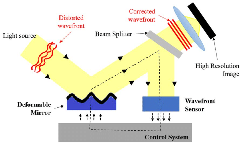
Generalized diagram of an adaptive optical system is as follows:
Wavefront from the observation object passes through the atmosphere and is distorted. It is then reflected from the deformable mirror and hits the “beam splitter”. One branch goes to the image recording and storage device. The other branch goes to the wavefront sensor, after which the signal enters the control system. An internal “wavefront corrector” corrects the spatial configuration of the mirror in such a way that...
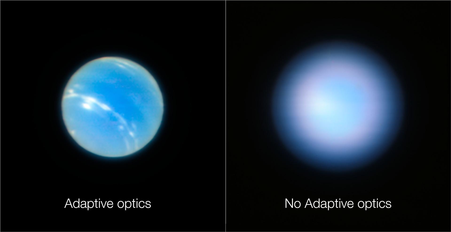
Here are the results of the adaptive optics system. For a single object:
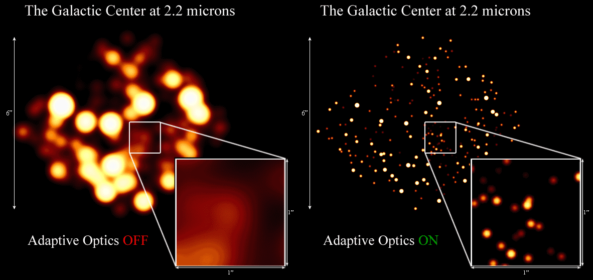
And for a group of observable objects:
This is where my question begins: how does a wavefront corrector work? Do I understand correctly that the control system “evens out” wavefront in the cross section of the electromagnetic wave, i.e. eliminates the difference in phase shifts, making the wave as flat as possible? How then is the “flatness” of this wave assessed? For this purpose, are some indicators of the quality of the adaptive optic system’s operation (Strehl number or others) used? Or is some indicator being maximized/minimized?
Generally speaking, how does the system understand that the image is of high quality (in the case of single and multiple observation sources)?
My research: I found several literature sources, including:
- Robert Tyson. Adaptive Optics Engineering Handbook.
- Zhizheng Wu, Azhar Iqbal, Foued Ben Amara. Modeling and Control of Magnetic Fluid Deformable Mirrors for Adaptive Optics Systems.
- John W. Hardy. Adaptive Optics for Astronomical Telescopes.
Unfortunately, 1-st sources do not contain a detailed practical description of the technical aspects of the operation of adaptive optics under consideration. And 2-nd and 3-rd are too difficult to understand at a beginner level.
Clarifying this aspect is critical to understanding the practical functioning of such systems and may be useful to programmers/mathematicians who develop them.
UPDATE. What do I mean and how do I imagine the answer to my question:
The undistorted wavefront (WF) is usually represented as a matrix $M$ (or another object, the structure of which is determined by the physical properties of the object of observation)... The WF passes through the “atmosphere” and is distorted to $M_{dist}$ (described either by a linear $M_{dist}=T*M$ or a more complex transformation $M_{dist}=T(M)$)... When we get to the WF sensor, we receive information about the WF distortions in the form of a matrix $D$ (it can also be another math-object, it all depends on the type of sensor)... By the matrix $D=F(M_{dist})$ we calculate the distortions $d=F(M_{dist})$ and compare them with the reference waveform shape (this can be either a pre-recorded reference matrix $M_{ref}$, or a waveform measured in parallel to a reference undistorted object (star,laser or planet), or something else)...We calculate the error $e=F(M_{dist},M_{ref})$ (it should be clarified exactly how to calculate it)...The error $e$ is converted into a matrix or vector of voltages $U$ for the drives of the deformable mirror... Using the resulting shape of the mirror $W$, we calculate the resulting WF and compare it with the reference $M_{ref}$... Also, instead of the error, we can calculate the integral indicator $I$ of the quality of the AO system (Strehl number, intensity, or something else)... We feed it to a block that maximizes/minimizes the required indicator(s) (i.e. $I \rightarrow max(Cost Function)$)... and selects the drive voltages $U$ accordingly...We use the following as optimization algorithms...
Naturally, the answer must be based on real applications and physical principles.


