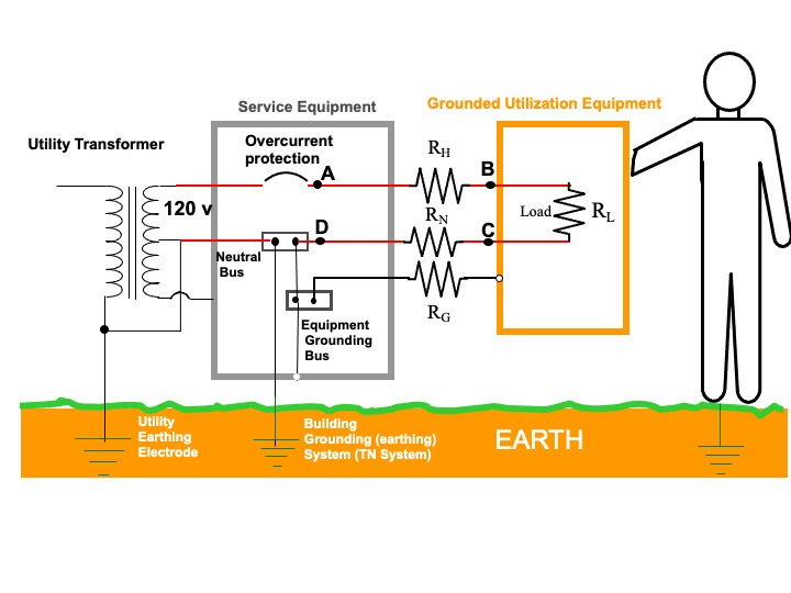
For the following, refer to the diagram below. For simplicity it shows a single dedicated branch circuit supplying a 120 vac load. Most branch circuits supply multiply general lighting and receptacle outlets.
So by that logic, both the hot and neutral have similar resistance AND
current.
In the diagram $R_H$, $R_N$ and $R_G$ represent the lumped hot, neutral, and grounding conductor wire resistances, respectively, between the branch circuit overcurrent device and the load. For simplicity we will ignore the resistance of the connections along the way and make the assumption those connections are properly made.
The resistance of the circuit conductors are essentially the same as they use the same size (gauge) wire and the lengths of the runs are the same as they are contained in a single cable. The load current is carried by the hot and neutral conductors (path shown in red) and is the same for both.
Adding a wire into the ground does not change current and resistance
overall.
I assume the "wire" you are referring to is the equipment grounding conductor. Since that wire, as shown in the diagram, is independent of the current carrying conductors it does not carry load current (it only caries fault current if the hot circuit contacts the equipment grounded parts). So it has no effect on the resistance in the current carrying conductors, including the neutral.
Can someone explain looking at voltage this way and how the neutral is
still near 0? I think I am mis-understanding this concept.
It's not clear exactly what you mean, but let's refer again to the diagram. I have labeled points A, B, C and D. Ignoring the resistance of the service entrance conductors to the left of the service panel (which are much less than the resistance in the branch circuits). Assuming a load current of $I$, applying Kirchhoff's voltage law we have
$$120 - IR_{H}-IR_{L}-IR_{N}=0$$
Of interest to you is the voltage to ground on the neutral conductor. Note that the voltage to ground on the neutral at point D, where the neutral is bonded to ground, is essentially zero. But the voltage on the neutral at point C with respect to ground is not zero because there is a voltage drop across the resistance $R_N$ in the neutral circuit. However, how much greater depends on the load current and $R_N$. So let's put some numbers on it.
In the US a 15 ampere branch circuit requires a minimum 14 AWG copper wiring. That wire has a resistance of about 0.25 Ohms per 100 feet. Let's say the load is maxim allowed for the branch circuit, 15 amperes. Then, from Ohms law $V=IR$ the voltage drop along a 100 foot run of the neutral wire is V=(15)(0.25)= 3.75 volts. This means that point C on the neutral would be 3.75 vac above ground.
Hope this helps.


