0
$\begingroup$

I have researched and asked some questions around this before, so let me explain. I understand by bonding an Earth ground (literally a green wire to a metal rod in the ground) to the neutral bus bar, basically the voltage difference between ground and a neutral wire is almost 0 (yes assuming no improper wiring). But my brain can't work that way, I need explanations to all the small questions or it doesn't make sense. So Ohm's law states V=IR. In an imbalanced load, all the current on a hot wire through say a lamp goes back through the neutral. So by that logic, both the hot and neutral have similar resistance AND current. Adding a wire into the ground does not change current and resistance overall. Can someone explain looking at voltage this way and how the neutral is still near 0? I think I am mis-understanding this concept.

P.S. A picture/illustration may help, I kinda think of two big buckets of water with a pipe attached at the bottom and a big heavy turbine (a load) in the pipe, but then add a large water pump at the "hot" bucket. So being near the pump, but before the turbine on the "hot" side is more dangerous. Wondering if there is a better way to explain

$\endgroup$
8
  • 1
    $\begingroup$ This belongs on Electrical SE. "In an imbalanced load, all the current on a hot wire through say a lamp goes back through the neutral" Huh? "So by that logic, both the hot and neutral have similar resistance AND current" What? You seem to be mixing up three phase and single phase by talking about balanced loads but then talking about nonzero current through the neutral. Balanced or not is something that only applies to 3-phase and when balanced there is zero neutral current. With single phase, 100% of the current on the hot wire returns over the neutral under normal conditions. $\endgroup$
    – DKNguyen
    Commented Jan 17, 2022 at 15:49
  • 1
    $\begingroup$ And just in case: three phase does NOT mean hot, neutral, and ground. That's just single phase. Three phase is three hot wires, one neutral which might be omitted, and ground. $\endgroup$
    – DKNguyen
    Commented Jan 17, 2022 at 15:50
  • 1
    $\begingroup$ Re, "Adding a wire into the ground does not change current." That is correct. The "Earth" wire is not supposed to carry current. Its purpose is to keep the voltage of the system from "floating" with respect to Earth. $\endgroup$ Commented Jan 17, 2022 at 16:53
  • $\begingroup$ @Solomon Slow Yes that was kinda my point as if I understood correctly if we remove earth ground then the voltage on say the neutral would go up in relation to Earth. So in short the Earth ground keeps the neutral close to 0 $\endgroup$ Commented Jan 17, 2022 at 20:11
  • $\begingroup$ @ZackFrizzell, If we remove all of the Earth grounds (there's at least one in every building, and there are many others throughout the distribution system,) then the voltage on any of the wires with respect to Earth would be undefined. That is to say, the voltage would not depend on anything that was connected to the circuit. It would depend more on things like atmospheric electricity (e.g., like what causes lightning, only less so) which can charge isolated overhead wires to thousands of Volts W.R.T. Earth. $\endgroup$ Commented Jan 17, 2022 at 20:17

2 Answers 2

2
$\begingroup$

Ohm's law still holds, but I think you may be misunderstanding the purpose of a ground wire & its relationship to the neutral.

In an ideal world, when we apply a voltage to a load with our "hot" wire, we assume all the voltage drop occurs across the load, and none appears across the wires to and from that load. This would mean that the voltage on the neutral (also called the return wire) is automatically zero at all times, and automatically equal therefore to our reference: the ground potential.

If this were true we could dispense with the return wire and simply drive a copper rod into the ground right next to the load and connect the return side of the load to it. But a hundred miles of dirt leading all the way back to the power plant is not a good conductor, and the transmission losses would be really big. So we furnish a neutral return wire instead and run it all the way back to the power plant along with the hot wire.

Now that return wire should be at zero potential, but because a hundred miles of return wire has some (small) resistance, there will be a (correspondingly small) voltage drop across it and right next to the load, the voltage of the return wire will be perhaps a volt for example above ground while it is carrying the load current.

If the load current is 1000 amps and the return voltage is one volt, we will have an electrical arc welder on our hands if the return wire ever fails anywhere along its length- and when the wire burns out at that point, the return line voltage at the load jumps up to the source voltage and now both sides of the load are hot.

This means the load now presents a shock hazard and we have started a fire at the break in the return line.

The purpose of the third (ground) wire is to provide an emergency path to ground in case a short circuit occurs in the load or a fault arises in the return line for any reason. Normally, zero current flows through the ground line and all the load current flows through the return at near-zero voltage, and Ohm's law is satisfied- in the approximation that the load resistance is much greater than the return line resistance.

$\endgroup$
1
  • $\begingroup$ Ok marked this as the answer. I think I am getting it now pretty clearly. If we think of this like a DC circuit, it always has amps going back to the battery, but voltage drops. Only big difference in that and single phase AC is the higher voltage and that it's polarity changes. But since it changes with relation to the hot wire, the neutral is basically always like the return of the load or the side of a battery after a load. Thank you for your help! $\endgroup$ Commented Jan 17, 2022 at 20:07
1
$\begingroup$

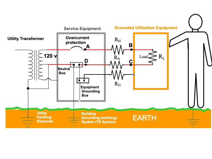
For the following, refer to the diagram below. For simplicity it shows a single dedicated branch circuit supplying a 120 vac load. Most branch circuits supply multiply general lighting and receptacle outlets.

So by that logic, both the hot and neutral have similar resistance AND current.

In the diagram $R_H$, $R_N$ and $R_G$ represent the lumped hot, neutral, and grounding conductor wire resistances, respectively, between the branch circuit overcurrent device and the load. For simplicity we will ignore the resistance of the connections along the way and make the assumption those connections are properly made.

The resistance of the circuit conductors are essentially the same as they use the same size (gauge) wire and the lengths of the runs are the same as they are contained in a single cable. The load current is carried by the hot and neutral conductors (path shown in red) and is the same for both.

Adding a wire into the ground does not change current and resistance overall.

I assume the "wire" you are referring to is the equipment grounding conductor. Since that wire, as shown in the diagram, is independent of the current carrying conductors it does not carry load current (it only caries fault current if the hot circuit contacts the equipment grounded parts). So it has no effect on the resistance in the current carrying conductors, including the neutral.

Can someone explain looking at voltage this way and how the neutral is still near 0? I think I am mis-understanding this concept.

It's not clear exactly what you mean, but let's refer again to the diagram. I have labeled points A, B, C and D. Ignoring the resistance of the service entrance conductors to the left of the service panel (which are much less than the resistance in the branch circuits). Assuming a load current of $I$, applying Kirchhoff's voltage law we have

$$120 - IR_{H}-IR_{L}-IR_{N}=0$$

Of interest to you is the voltage to ground on the neutral conductor. Note that the voltage to ground on the neutral at point D, where the neutral is bonded to ground, is essentially zero. But the voltage on the neutral at point C with respect to ground is not zero because there is a voltage drop across the resistance $R_N$ in the neutral circuit. However, how much greater depends on the load current and $R_N$. So let's put some numbers on it.

In the US a 15 ampere branch circuit requires a minimum 14 AWG copper wiring. That wire has a resistance of about 0.25 Ohms per 100 feet. Let's say the load is maxim allowed for the branch circuit, 15 amperes. Then, from Ohms law $V=IR$ the voltage drop along a 100 foot run of the neutral wire is V=(15)(0.25)= 3.75 volts. This means that point C on the neutral would be 3.75 vac above ground.

Hope this helps.
enter image description here

$\endgroup$

Your Answer

By clicking “Post Your Answer”, you agree to our terms of service and acknowledge you have read our privacy policy.

Not the answer you're looking for? Browse other questions tagged or ask your own question.