I'm not sure I completely understand your question, however, it is important to distinguish between emf, voltage drop, and potential difference.
First, let's distinguish emf and voltage drop.
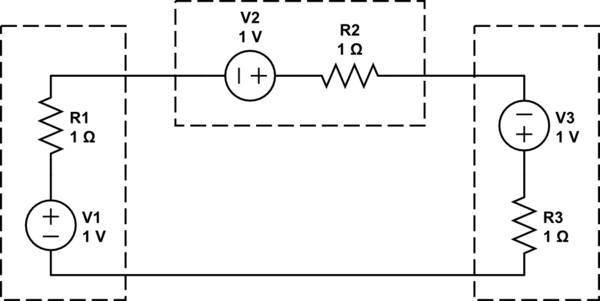
Consider the circuit below.

In this schematic, the resistance and voltage source R1 and V1 are meant to belong to the same physical component. Similarly for R2 and V2, and R3 and V3.
The total emf around the circuit is 3V. By Ohm's law and KVL, the total current in the circuit is 3V/3$\Omega$ = 1A.
However the voltage drop across each component will be
- the 1V voltage source minus
- a 1V voltage drop across the associated resistor (1A x 1$\Omega$)
or 0 volts.
So clearly, there is a difference between the voltage drop along some path between two points, and the emf acting along that path.
In the case of induction, we can define the emf along a path $C$ as
$$ \mathscr E_{induced} = \int_C \vec{E_{rot}} \cdot d\vec{\ell}$$
Where $\vec{E_{rot}}$ is the divergence-free (or rotational) $E$ field induced by the time-varying magnetic $B$ field.
The voltage drop, along path $C$ is the EMF along the path minus the current times the resistance of the path. (Assuming a simple "Ohm's law" relationship.)
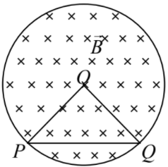
In the case of a uniform conductive loop with a centered time-varying magnetic field, the voltage drop between any two points on the loop will be 0. The emf will be non-zero.
Although it is not a major part of your question, I think it is also important to point out the distinction between a voltage drop between two points along a path, and a potential difference. If the voltage drop between two points is path independent, then we speak of a potential difference. Such will be the case whenever the circuit is not influenced by a time-varying magnetic field. However, when there is a time-varying magnetic field, the voltage drop between two points will, in general, depend upon the path. In that case, referring to a "potential difference" between two points risks making a conceptual error, which is likely to result in a mathematical error.


