When you apply a force to an extended object (with density profile $\rho(\vec r)$), you can treat is as accelerating the center of mass:
$$ r_{i,\, cm} = \frac{\int_Vr_i \rho(\vec r)d^3r}{\int_V\rho(\vec r)d^3r}$$
The numerator is the 1st moment of the mass distribution.
The denominator, which is the zeroth moment, is just the total mass:
$$ m = \int_V\rho(\vec r)d^3r$$
If that force acts from a point, $\vec r_0$, then there is also a torque:
$$ \tau_i = \epsilon_{ijk}(r_{j, 0} - r_{j, cm}) F_k $$
(Sorry for the index notation, but it has a purpose). The torque leads to a changing angular momentum:
$$ \dot L_i = \tau_i $$
with
$$ L_i = I_{ij}\omega_j $$
where the inertia tensor is related to the 2nd moment of the mass distribution:
$$ I_{ij} = \int_V (r^2\delta_{ij}-r_ir_j)\rho(\vec r)d^3 \vec r$$
So you get acceleration and torque of this mass distribution simplified down to a motion of and rotation around, a point.
What if that force is caused by gravity, in a non-uniform field?
The temptation is just find the g-weighted 1st moment:
$$ r_{i,\,cg} =\frac 1 m \int_V{ \rho(\vec r)g(r)r_id^3 r }$$
In a uniform field, it reduces to the center-of-mass. In a uniform gradient, it works well, too.
But there is a problem: $g(r)$ is supposed to be a vector, and if I put in index on it, as in $g_j(r_i)$, in the integral: there is no way to get rid of the $j$ and come out with a vector on the RHS to match the $i$ indexing the vector on the LHS.
You could define a CG for each component of the field:
$$ r_{i,\,j-cg} =\frac 1 m \int_V{ \rho(\vec r)g_j(\vec r)r_id^3 r }$$
and hope they are all equal. The difficulties related to this are addressed in https://en.wikipedia.org/wiki/Centers_of_gravity_in_non-uniform_fields, which I will not repeat, but in summary, it says the CG is the point about which a force needs to be applied to give the correct torque....which may not be unique, nor even defined, in all cases.
In practice, field configurations do admit a center-of-gravity, in which the motion can be described from a potential energy:
$$ U(\vec r_{cm}) = m\phi(\vec r_{cm}) $$
and the force is the gradient:
$$ F_i = -\nabla_i U=m\nabla_i\phi $$
Rotation depends on the quadruple moment:
$$ Q_{ij} = \int_V{(3r_ir_j-r^2\delta_{ij})\rho(\vec r)d^3r}$$
coupling to the gradient of gravitational field:
$$ U = Q_{ij}\nabla_i\nabla_j\phi $$
which leads to a torque versus angle. (Note: being a tensor moment, it has 4 extrema with respect to orientation, while a dipole as 2: aligned and anti-aligned.)
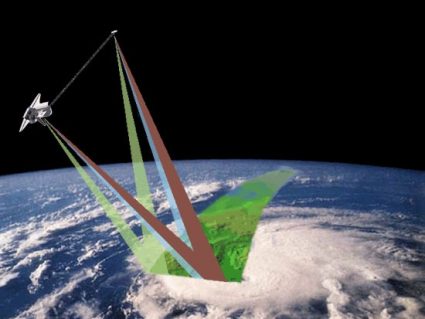
A classic example of this is the Shuttle Radar Topography Mission (SRTM):

There are 2 masses (the shuttle and an antenna) on each end of a 60 meter boom. In the operational configuration, the boom is roughly 45 degrees off vertical, which is the point of maximum instability. The heavier shuttle wants to be lower where the field is stronger.
In order to keep the system aligned, an attitude correction was applied every 20 minutes. The original design was a compressed nitrogen jet at the antenna (see question 3) applying a small correcting torque.

