5
$\begingroup$

I am analyzing an optical system two different ways. One way is using the image formation formula:

$$ \frac{1}{d_0} + \frac{1}{d_i} = \frac{1}{f} $$

and the other is using the Fourier transform property of a lens. That is, if a 2D object is at position $-f$ with respect to a lens then the 2D Fourier transform of the object will appear at position $+f$ on the other side of the lens.

Consider the following imaging system. I imagine the object to be on the left and the camera to be on the right.

  • An object is at position $0$.
  • Lens 1 with $f_1$ (the objective) is distance $f_1$ from the object.
  • Lens 2 with $f_2$ (the relay lens) is distance $f_1 + 2f_2$ from the first lense.
  • Lens 3 with $f_3$ (the imaging lens) is distance $f_3+2f_2$ from the second lens.
  • A screen or camera is placed distance $f_3$ from the third lens.

Fourier transform approach:

Analyzing the system from the point of view of the Fourier transform:

Under this mode of analysis we deduce that the back focal plane of the first lens ($f_1$ to the right of the objective) is a Fourier transform of the object. This Fourier plane is then distance $f_2$ to the left of the second lens. This means (by the image formation formula) that a $1:1$ copy of this Fourier plane is recreated distance $f_2$ to the right of the second lens. This second Fourier plane is then distance $f_3$ to the left of the third lens so distance $f_3$ to the right of the third lens we should find an object plane again (the Fourier transform of the Fourier plane). Thus under this analysis we expect an image to form on the camera.

Image formation approach:

In this approach the object is distance $f_1$ from the first lens. This means the light coming from the object is "collimated" telling us that the image is formed at (negative) infinity. The second lens then (no matter the distance between the first and second lens) forms a real image of the prior image at infinty distance $f_2$ to the right of the second lens. This real image is then distance $f_2+f_3$ to the left of the third lens. The image formation formula for the third lens is then:

\begin{align} \frac{1}{d_i} + \frac{1}{f_2+f_3} &= \frac{1}{f_3}\\ d_i &= \frac{f_2+f_3}{f_2} f_3 > f_3 \end{align}

So we see that instead of having an image appear $f_3$ to the right of the first lens an image forms further away than $f_3$.

Summary

So we see that calculation under the two approaches results in different answers for the where the image is formed.

I can't find a flaw in the reasoning of either approach so I am thoroughly confused. Can someone please help me resolve the paradox and let me know where I am going wrong?

The only lead I have is that perhaps in this sort of imaging system the approximations necessary for the Fourier transforming property of the lens to hold true are not satisfied?
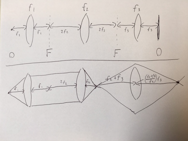
Here is a janky sketch of what I am talking about. In the upper image the $O$ and $F$ symbols denote object and Fourier Planes. In the lower image I have done a rough ray tracing of an on-axis point.

$\endgroup$
0

3 Answers 3

2
+100
$\begingroup$

You are right that the second lens does image the amplitude of the Fourier back-focal plane of the first lens to its own backfocal plane, but it changes its phase along the way!! This means your first drawing is incorrect from the second lens onwards. To really get it right, you have include the complex transfer function of a lens $$a(x,y) \sim e^{-i\pi \frac{x^2+y^2}{\lambda f}}$$(see the notes here).

In more detail, the optical field $2f_2$ to left of the second lens is given by

$$\psi(x,y,z=2f_2) = A(x,y) e^{i\phi(x,y)}$$

At the backfocal plane ($2f_2$ to the right of the second lens), you get

$$\psi'(x,y,z=-2f_2) = A(-x,-y) e^{i\phi'(x,y)}$$

Which is to say the object undergoes a magnification of $-1$ across the second lens.

So while it is true that the intensity pattern $I(x,y) = \vert \psi(x,y)\vert^2$ at $+2f_2$ and $-2f_2$ are identical (modulo overall inversion), their phases are very different in general $\phi(x,y) \neq \phi'(x,y)$. If you send $\psi'(x,y)$ through the third lens with the full transfer function formalism, you will find that it does not result in the initial object, in contrast to your first image.

The two optical fields before and after the second lens will only be identical (modulo inversion) under "plane wave illumination" conditions where $\phi(x,y)=\mathrm{const.}$ and thus $\phi'(x,y)=\mathrm{const.}$. This is why you need a setup like that shown in Figure 1 of these notes to get the Fourier transform property to work in practice.

$\endgroup$
8
  • $\begingroup$ You have misinterpreted what I was trying to show in the first image. The idea is that the first lens creates a Fourier plane $f_1$ to its right. The second lens then reimages this Fourier plane from $2f_2$ to its left over to $2f_2$ to its right. This is justified actually based on the image formation formula that I linked which typically is derived from ray optics. So the first scenario is actually I guess a combination of ray and Fourier/wave optics. However, I think the $\frac{1}{d_o} + \frac{1}{d_i} = \frac{1}{f}$ formula can also be derived in Fourier/wave optics. $\endgroup$
    – Jagerber48
    Commented Jan 27, 2020 at 1:29
  • $\begingroup$ However, your clarification that ray optics is derived from and an approximation of wave optics is helpful. It is also my feeling that the Fourier optics should be more "trusted". Of course, I don't know all of the approximations necessary for ray optics to work or for the Fourier transform property of the lens to hold etc. $\endgroup$
    – Jagerber48
    Commented Jan 27, 2020 at 1:30
  • $\begingroup$ I see, so actually what is going on is that you are misapplying the Fourier transform property of a lens by combining it with the ray optics formalism in an inconsistent way. While it is true that if you put a camera at $+2f_2$ and $-2f_2$ relative to the second lens then you would see the same image (modulo it being inverted). $\endgroup$
    – KF Gauss
    Commented Jan 27, 2020 at 2:18
  • $\begingroup$ But notice that the angles of the light for the images at $+2f_2$ and $-2f_2$ are not the same. In Fourier optics you need to account for both the spatial intensity of the light, as well as its angular distribution (how the light is "pointing"). Two sources with the same spatial intensity but different angular distribution at $+f$ will not produce the same Fourier transform at $-f$, which should make sense. $\endgroup$
    – KF Gauss
    Commented Jan 27, 2020 at 2:18
  • 1
    $\begingroup$ Long story short, you only get a Fourier transform of the spatial intensity at $+f$ on the other side of the lens at $-f$ if it is illuminated with parallel light (see Figure 1 of phys.unm.edu/msbahae/Optics%20Lab/Fourier%20Optics.pdf). Otherwise you get a more complicated convolution of the spatial Fourier transform and angles. $\endgroup$
    – KF Gauss
    Commented Jan 27, 2020 at 2:39
2
$\begingroup$

Throwing in my own answer that I found after the helpful hints from the other answers. See "Introduction to Fourier Optics" by Joseph Goodman, chapter 5 as well as the reference cited there: M. Nazarathy and J. Shamir, "Fourier optics described by operator algebra," J. Opt. Soc. Am. 70, 150-159 (1980)

Goodman introduces a nice operator notation that makes it very easy to evaluate wave propagation in the Fresnel/paraxial limit. Here we wish to calculate the wave propagation from the first Fourier plane in the images in the OP to the purported "image" of the Fourier plane. This is just analysis of a single lens imaging system.

The idea is that at the input to the system we have some scalar field $U_0(x,y)$ and we wish to calculated the field at the output, $U_f(x,y)$, after the field has propageted through free space and optical components such as lenses. The idea is that

$$ U_f(x,y) = SU_0(x,y) $$

Where $S$ is some general operator acting on the input field. $S$ may be a cascade of multiple operators such as free space propagation and passage through lenses. Goodman introduces some useful operators to aid in these calculations:

  • $R[d]$, propagation in free space of distance $d$: \begin{align} R[d]U(x,y) =& \frac{1}{ijd} \int U(x', y') e^{i\frac{\pi}{\lambda d} ((x-x')^2 + (y-y')^2)} dx' dy'\\ =& (U \ast g_d)(x,y) \end{align} where $\ast$ indicates convolution and the Fresnel propagation kernal is $$ g_d(x,y) = \frac{1}{ijd} e^{i\frac{\pi}{\lambda d}(x^2 + y^2)} $$

  • $Q[c]$, multiplication by a quadratic phase factor:

$$ Q[c]U(x,y) = e^{i\frac{\pi}{\lambda} c(x^2 + y^2)} U(x,y) $$

  • $V[b]$, rescaling of a function:

$$ V[b]U(x,y) = \frac{1}{b}U(bx, by) $$

  • $\mathcal{F}$ and Fourier transform:

$$ \mathcal{F}U(x,y) = \int U(x,y) e^{-i 2\pi(k_x x + k_y y)} dx dy $$

A lens of focal lenght $f$ enacts the quadratic phase operator, that is

$$ L[f] = Q\left[-\frac{1}{f}\right] $$

The system of propagation distance $d_1$, passage through a lens of focal length $f$, and then propagation again distance $d_2$ is given by (dropping some global phase factors)

\begin{align} S = R[d_2]Q\left[-\frac{1}{f}\right]R[d_1] \end{align}

We'll suppose that the image formation equation $\frac{1}{d_1} +\frac{1}{d_2} = \frac{1}{f}$ is satisfied (for example $d_1 = d_2 = 2f$).

I won't go through the detail here, but in both references a number of operator identities are demonstrated which allow the simplification of this system to

\begin{align} S = Q\left[\frac{d_1+d_2}{d_2^2}\right]V\left[-\frac{d_1}{d_2}\right] \end{align}

This tells us that the image at the final plane is a version of the original image just rescaled (as indicated by the $V$) by the magnification $M = -\frac{d_1}{d_2}$ and with the additional phase factor described by the $Q$.

This is exactly the additional phase factor described in the previous answers, this just gives a quantitative measure of how large that phase factor is. In cases in which only the magnitude of the final signal is of interest it is clear that this phase factor will have no effect. I think this is why it never comes up in discussions of ray optics. However, when wave optics are considered, and especially Fourier transform optics, these phases can spoil the Fourier transform.

$\endgroup$
1
1
$\begingroup$

Ray optics and wave optics are equally able to describe your optical setup. Wave optics is just additionally able to describe effects of interference, diffraction and polarization. This makes it necessary to always consider intensity and phase when using the wave model. The phase is what you do not considered when describing the effect of the second lens which leads to an incorrect result for the wave optics approach. The Fourier transform formalism can be used to describe the connection between the wave field in the front focal plane of a lens with the wave field in the back focal plane. To get to different distances to the lens you have to calculate the according propagation of the wave field for which you have to use intensity and phase of the wave field.

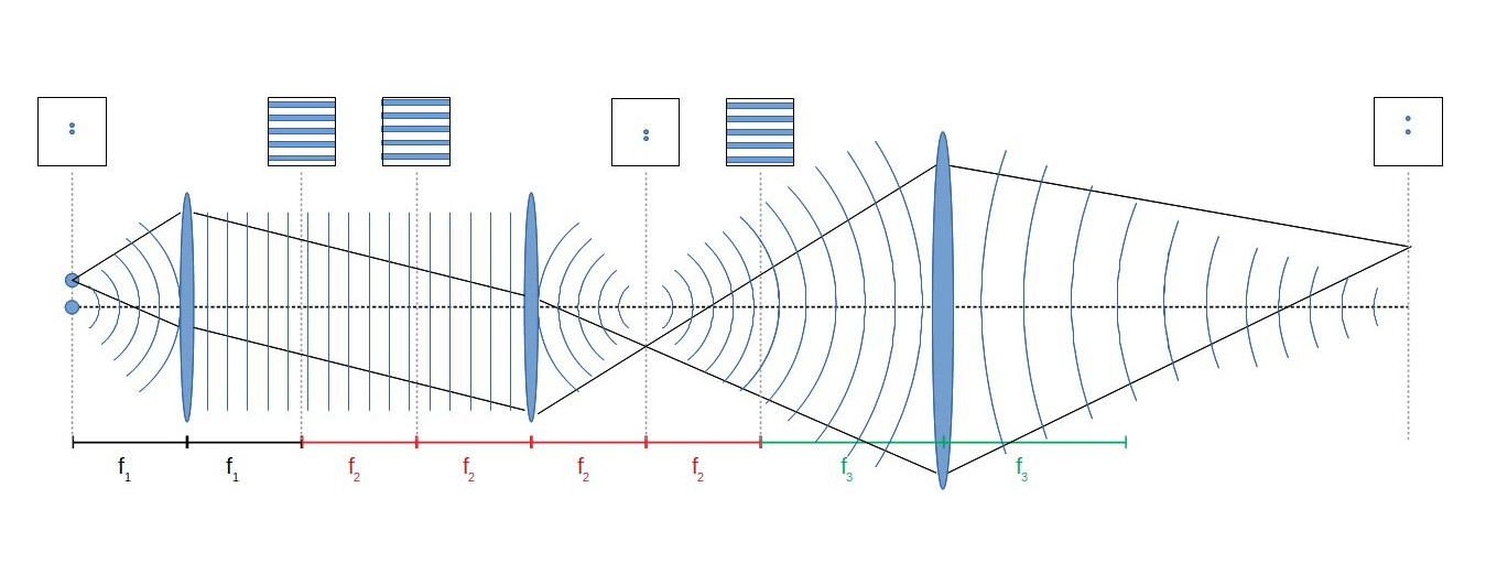
The example of a simple wave field consisting of two wavefronts might illustrate what is happening in the optical system you describe:

Lets assume two point light sources in the object plane. One point light source on the optical axis and one at a distance to the optical axis. Both emit a spherical wavefront which will hit the first lens. This lens converts the spherical wavefronts to plane wavefronts (i.e. collimates the light) since the object plane is at focal distance to the first lens. The light from the second light source (the second wavefront) is a tilted plane wave after the first lens (i.e. the collimated light has an angle to the optical axis) because the second light source is not located on the optical axis. Both wavefronts do not change shape when propagating to the back focal plane of the first lens (effects of lens apertures are ignored here for simplicity). The interference pattern of two plane waves at an angle shows straight fringes of equal distance. Such sine-shaped intensity patterns are the spatial frequencies which are described by Fourier theory. (Reversing the direction of the light and the Fourier transformation shows that the off-axis spot (i.e. the second point light source) is the Fourier representation of the spatial frequency of the interference pattern.)

The two wavefronts then propagate further to the front focal plane of the second lens, still keeping their shape and direction since this is the property of plane wave propagation in free space. You can now use the Fourier transform approach to get to the back focal plane of the second lens (in principle the reverse operation as with the first lens) or use the property of lenses that they transform a plane wave to a spherical wave with a radius of curvature of the focal length of the lens. A positively curved spherical wavefront converges to a point at its center of curvature. Either way you get two light spots at the back focal plane which are the images of your object as you already showed with the ray model and the image formation formula.

beam paths

At the position $2f_2$ behind the second lens, two spherical wavefronts interfere. This gives a pattern of straight fringes (see e.g. here on page 2.13). This is an image of the interference pattern $2f_2$ before the second lens concerning the intensity distribution but it is not a copy of the wave field since the phase distribution is obviously completely different. That is the mistake in your description of the fourier imaging that the you equate intensity distribution and wave field.

The third lens generates an image of the two light spots $f_2+f_3$ in front of the third lens. It is a lengthly calculation to describe the image formation of the third lens with wavefront propagation and Fourier theory. For complex images it is usually done with numerical wavefront propagation algorithms. The math for this is sketched in the answer from jgerber. I will skip this since we already saw that the wave model gives the same result for image formation as the ray model. A simplified visual description would be that the light from the point light sources will form a spherical wavefront with radius of curvature of $-(f_2+f_3)$ at the position of the third lens. The lens would turn a spherical wave of radius of curvature of $-f_3$ into a plane wave but since we have a wavefront with less curvature, the lens sort of overcompensates and generates a spherical wavefront of positive radius of curvature. This wavefront then converges to a point at a position beyond the back focal plane of the third lens. As already said, this position of the image is more easily calculated with the image formation formula as you did in your text of the question.

$\endgroup$

Your Answer

By clicking “Post Your Answer”, you agree to our terms of service and acknowledge you have read our privacy policy.

Not the answer you're looking for? Browse other questions tagged or ask your own question.