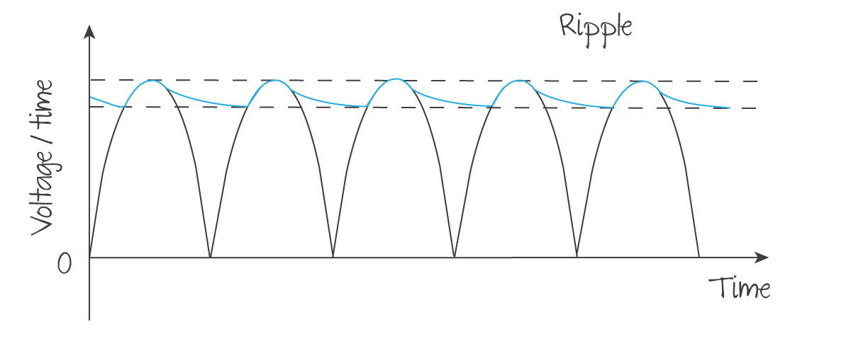
Why is this the case? I thought a higher resistance results in a
slower voltage discharge rate, so wouldn't we want to increase the
discharge rate of the capacitor, hence a lower resistance load?
Yes the higher the load resistor connected across the output of the rectifier the slower the discharge rate, all other things being equal.
But no we wouldn't want to increase the discharge rate of the capacitor. We want to decrease it. It sounds like you think the capacitor is in series with the load resistor connected to the output of the rectifier. It is not. Both the load resistor and capacitor are connected in parallel across the output of the rectifier.
The idea of using the capacitor is to connect it in parallel with the output of the rectifier in order to keep the output voltage of the rectifier to the load resistor in between successive cycles close as possible to the upper hashed line, which is the peak output voltage of the rectifier. The faster the discharge rate of the capacitor (the steeper the slope of the solid curves), the quicker the capacitor voltage drops to the voltage of the bottom hashed line, below the peak output voltage of the rectifier.
Bottom line: For a given load resistance connected across the output of the rectifier, the larger the capacitor (i.e., the greater the charge per volt across the capacitor), the closer the rectifier output will come to its peak output voltage, shown by the upper hashed line.
Hope this helps.

