2
$\begingroup$

Okay, this would probably seem a pretty basic doubt but I can't understand this thing. I know that when the current is not flowing in the battery the voltage across the terminals is the emf of the battery but when current flows then we need to take into account the internal resistance.

Now, my doubt is that, if we consider only the external resistance, then the current should have been greater than it would have been in the absence of internal resistance. So, I want to know the behavior of the instantaneous current (just when the switch is connected) in the case when internal resistance is there.

Does the current instantly have a value of $\frac{V}{R+r}$ where V is the emf of the cell and R and r are the external and internal resistance respectively? Or does the current initially have the value $\frac{V}{R}$ and then it decreases (at a rate too fast for humans} and reaches the value $\frac{V}{R+r}$ at a steady state?

The reason I got the idea in the second interpretation is that I thought the potential difference across the external resistance just when the switch is connected is the battery's emf (I may be wrong), so the current initially must be the potential difference divided by resistance.

Context:

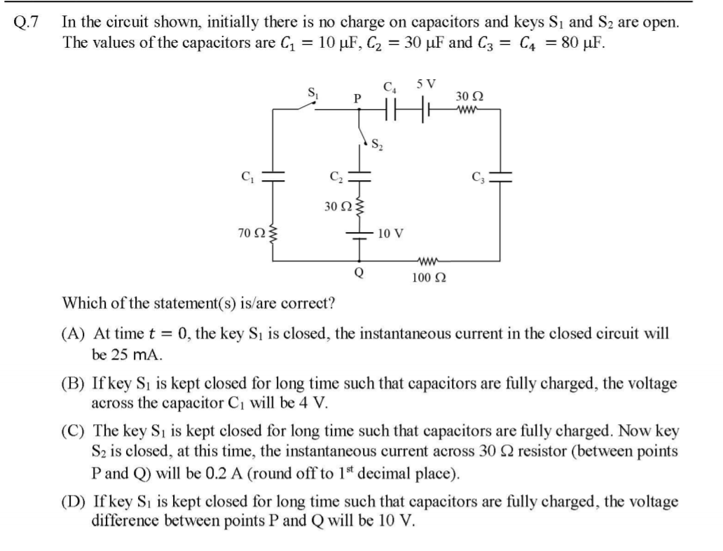
Okay, this doubt came to me from trying to solve this question in JEE Advanced 2019 Paper 1

enter image description here

The answer is given as A, B and C (it is a one or more than one option correct question) in the official answer key. (Which I think, is correct)

Now, the answer given by many people is A and B only, which is also backed by many renowned coaching institutes in India.

Coming to option C, what I did was that when switch $S_1$ is connected and steady state is reached the potential difference across P and Q is 4V and there is also a cell of 10V in series in the opposite direction in that branch. So the resultant voltage across the 30 ohms resistance just at the instance of closing the switch $S_2$ is 6V so the current just at the moment of closing the switch is $\frac{6}{30} = 0.2$.

While others did this. They replaced the capacitors with equivalent cells which gives a circuit equivalent to two 4V cells with internal resistances 70 and 130 respectively and then they used the formula for the parallel combination of resistors and got an answer other than $0.2$ $(0.079)$.

If I put my approach in the context of the others approach, I did assume something that instantaneously the current does not flow through the branches of 130 ohms and 70 ohms resistance initially. OR in other words, I thought of not including the internal resistance in my interpretation of instantaneous current. The whole thing boils down to what I've asked in my main question.

$\endgroup$
3
  • $\begingroup$ To be sure, for any physical circuit, there is inescapable inductance (capacitance) which implies that the currents (voltages) cannot instantaneously change just when the switch is connected. So, is your question in the context of ideal circuit theory where the circuit is, in this example, in ideal voltage source in series with an 'internal' ideal resistance, ideal switch, and ideal load resistance? $\endgroup$ Commented Jun 5, 2019 at 1:04
  • $\begingroup$ @AlfredCentauri No, my question is completely theoretical. So, I'm not counting any inductances. $\endgroup$ Commented Jun 5, 2019 at 1:12
  • $\begingroup$ @AlfredCentauri I've edited my question to provide some context to what I mean by my question, in case you want to look at that. $\endgroup$ Commented Jun 5, 2019 at 1:32

4 Answers 4

1
$\begingroup$

I think that the point that you are missing is that the ideal circuit diagram that you have drawn is an approximation of a real life situation and so you should be wary of going outside of the limits of the approximations which you have (unknowingly?) made.

Consider a very simple circuit of a cell of emf $\mathcal E$ connected in series to an open switch and a resistor of resistance $R$.
You are asked for the current in the circuit when the switch is closed and you would probably give the answer as $\frac {\mathcal E}{R}$ and have you answer marked as correct.
In the ideal world of your calculation you have assumed that the current can change instantaneously from zero to $\frac {\mathcal E}{R}$.
In the real world this cannot happen - think of it as electrons having mass and accelerating from zero velocity to a finite velocity instantaneously.
There is nothing wrong with your answer of $I = \frac {\mathcal E}{R}$ as long as you realise that this is the current a finite time (but very, very small compared with the response time of any current measuring instrument that you might use) after the switch has been closed.
If you want to know more about what happens you must consider the circuit as being more complex than just having a cell, a switch and a resistor and introduce the idea that there is also (parasitic) capacitance and inductance in the circuit.
If you do this then you can show that the current takes a finite time to reach its final value.

So with your cell, emf $\mathcal E$ with internal resistance $r$ in series with a resistor $R$ and capacitor $C$ you can say that the initial current after closing the switch is $\frac {\mathcal E}{R+r}$ because you are making the approximation that the current can change instantaneously and the initial potential difference across the capacitor is zero.

In you more complex circuit the current is allowed to change instantaneously but the change on a capacitor is not.

For consideration of option A to find the "initial" currents you can replace the capacitors with short circuits as they are uncharged initially and so do not have a potential difference across them.

For consideration of option B to find the "final" voltages you can replace the resistors with short circuits if they are in series with a capacitor as then the resistors will have no current passing through them and hence potential difference across them will be zero.

Consideration of option C is more complicated but you do know that the charge on the capacitors cannot change instantaneously which in turn means that nor can the potential difference across them.
This is why some solutions replace the capacitors with a cell with an emf equal to the initial potential differences across the capacitors as this might make the application of Kirchhoff's voltage law easier?

To sum up.
In the ideal circuit world (with no inductors present) the current can change "instantaneously" and so can the potential difference across a resistor, but the charge on a capacitor and hence the potential difference across a capacitor, cannot change instantaneously unless a capacitor is "shorted out".


PS - I do not think that option C is correct.

$\endgroup$
1
$\begingroup$

Does the current instantly have a value of $\frac{V}{R+r}$ where V is the emf of the cell and R and r are the external and internal resistance respectively? Or does the current initially have the value $\frac{V}{R}$ and then it decreases (at a rate too fast for humans} and reaches the value $\frac{V}{R+r}$ at a steady state?

If there is a substantial capacitance across the battery terminals, then you would have an initial current of $\frac{V}{R}$, since the potential across the terminal could not change instantaneously.

If you want to consider all elements as ideal with no parasitic elements, then the initial current would be $\frac{V}{R+r}$.

As third possibility, if you consider the parasitic inductance in the loop formed by the battery and the resistor, then the initial current is 0, and it can only increase at a finite rate determined by the parasitic inductance.

I'll leave aside analyzing the JEE problem, since you say you've only presented it for context.

One thing to consider, in this problem all the batteries have capacitors placed in series. This isn't likely to correspond to any real parasitic in the system you asked your main question about; it would only occur if you deliberately placed a capacitor in series with either the battery or the load resistor.

$\endgroup$
1
$\begingroup$

So the resultant voltage across the 30 ohms resistance just at the instance of closing the switch S2 is 6V so the current just at the moment of closing the switch is $\frac{6}{30}=0.2$.

This isn't a valid solution (in ideal circuit theory).

First, it is typical to consider the solution just before and just after the switch is closed rather than at the instant it is closed (which is somewhat ambiguous).

It's just not valid to assume that the voltage across the middle branch is $4 V$ just after the switch is closed. That would only be true if there were $0 A$ through the other resistances just after the switch is closed but, by KCL, there isn't $0 A$ through the other resistances if there is $0.2 A$ through the 30 ohm resistance. Thus, your solution isn't consistent.

Instead, the voltage across the middle branch is discontinuous at the closing of switch S2. Just before S2 is closed, the voltage across the middle branch is $4 V$ but there's nothing (in ideal circuit theory) that constrains that voltage to be continuous across the closing of switch S2.

$\endgroup$
2
  • $\begingroup$ No, I'm sorry. I mean just at the instant of closing the switch. (Sorry, if I'm sounding stupid again, I just want to understand this thing) $\endgroup$ Commented Jun 5, 2019 at 1:50
  • $\begingroup$ @ShubhraneelPal, I've edited my answer to address your edits. $\endgroup$ Commented Jun 5, 2019 at 2:49
-1
$\begingroup$

Does the current instantly have a value of V/(R+r) where V is the emf of the cell and R and r are the external and internal resistance respectively? Or does the current initially have the value V/R and then it decreases (at a rate too fast for humans} and reaches the value V/(R+r) at a steady state?

You can analyze this type of problem by considering a RC type of circuit, when you solve the differential equation you get enter image description here and when you differentiate the function enter image description here which is why the current rises to only E/R and not E/(R+r). Also note negative sign which signifies current is decreasing. A circuit with only resistor current shoots to this value E/(R+r) as electric field lines flows inside a wire with speed of light. So the time it will take light to flow in the circuit that much time it will take current to rise inside the circuit assuming other parameters are negligible.

$\endgroup$

Your Answer

By clicking “Post Your Answer”, you agree to our terms of service and acknowledge you have read our privacy policy.

Not the answer you're looking for? Browse other questions tagged or ask your own question.