1
$\begingroup$

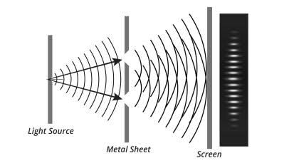
In the experiment of any wave through the double slit we see and model the interference pattern as shown.

enter image description here

In this depiction that means the wave propagates in/out of the page. ie we are seeing a sin wave from a bird’s eye view. I was under the assumption that all EM waves travel in all directions.

Consider in this image; LEFT-RIGHT - X Axis UP-DOWN - Y Axis IN-OUT of Page - Z Axis

this model shows a sin wave in the X-Z and Y-Z planes but not the X-Y plane. Does this sin wave not exist or get cancelled out in interference or what?

$\endgroup$
9
  • 1
    $\begingroup$ No, this picture shows that the waves are moving rightwards, i.e. your X axis, so the lines that are drawn are waves with their electric fields waving in the Y or the Z axes, because in light waves the E and B fields are perpendicular to the propagation direction. $\endgroup$ Commented Jul 11 at 6:13
  • $\begingroup$ For a very thin slit opening the electric field should be parallel to the slit (i.e. pointing along your z-axis). The near field solution is a mess, looking at some of the literature, the far field solution should be vertically polarized cylindrical wave fronts with the B field perpendicular to the E-field and the k-vector of the waves, if I am not mistaken. I think my intuition agrees with what @naturallyInconsistent said. There is a good reason why we usually only talk about diffraction in terms of scalar wave theory in Frauenhofer (far field) approximation. The real deal is complicated. $\endgroup$ Commented Jul 11 at 6:54
  • $\begingroup$ @FlatterMann Having done the experiment, albeit with a pair of slits I scratched on the back of a plane mirror, I saw the same interference pattern irrespective of the plane of polarisation of the incident light? $\endgroup$
    – Farcher
    Commented Jul 11 at 9:55
  • $\begingroup$ @Farcher Did you measure the polarization of the outgoing light? $\endgroup$ Commented Jul 11 at 9:57
  • $\begingroup$ @FlatterMann No, but the interference pattern intensity did not seem to change as I rotated the plane of polarisation. From the diffraction envelope I estimate the width of my slits to be approximately $50\,\mu\rm m$. Perhaps that is not narrow enough? $\endgroup$
    – Farcher
    Commented Jul 11 at 10:16

1 Answer 1

0
$\begingroup$

The diagram on the left is in the xy-plane and you can liken it to a contour map taken at an instant of time, like a photograph. Initially let me assume that the incoming light is plane polarised in y-direction.
The black lines show positions where the crests (maximum field in the y-direction) of the electric vectors of the electromagnetic waves occur.
However those black lines could equally well represent the crests of the light which was polarised in the z-direction or any other direction in the yz-plane.
What I am trying to explain is that to get an interference pattern the incoming light does not have to be plane polarised and your diagram or a ripple tank demonstration may give the opposite impression.

The diagram on the extreme right shows what the fringe pattern might look like in the yz-plane with the pattern in the z-dimension being there because you have stipulated that slits are being used, ie the interference pattern is three dimensional.

There is evidence that when Young did his experiments he used two holes and it that case the fringes generated in a yz-plane are hyperbolic as explained in the post Why is the shape of the fringes in Young's double slit experiment hyperbolic?.

As to what happens when the plane of polarisation of the light entering each of the slits differ I refer you to I polarize the slits (one H, the other V) of a Young's double-slit. If my source is H or V, do I see fringes? What about if my source is D or AD?.

$\endgroup$
0

Your Answer

By clicking “Post Your Answer”, you agree to our terms of service and acknowledge you have read our privacy policy.

Not the answer you're looking for? Browse other questions tagged or ask your own question.