1
$\begingroup$

This is a derivative of the question regarding the Sagnac effect. Judging from the metric $ds^2=-dt^2+(rd\phi)^2$ for a constant $r$ for this question, it should be no different from that on a line with replacement $x=r\phi$ and the circular setting should to be equivalent to the following setting on a straight line where $ds^2=-dt^2+dx^2$. There is a local homeomorphism between the circular and linear metric.

Assume the speed of light is $1$. A rigid rod of unit length measured in its own rest frame is moving with a constant velocity $\beta$ along its length from left to right with respect to an inertial lab reference frame. In the rod's own rest frame a light signal emitted from the left end of the rod towards the right end takes time $t_1=1$ to reach the target and takes the same time $t_2=1$ to go back. In the lab frame where the rod is moving, the light takes $t_1'=\frac1{\gamma(1-\beta)}$ going from the left end to the right and $t_2'=\frac1{\gamma(1+\beta)}$ to reverse the course.

However, while the round trip time $t_1'+t_2'=2\gamma=\gamma(t_1+t_2)$ is as expected from time dilation, the time differences $t_1'-t_2'\neq\gamma(t_1-t_2)=0$ where the opposite is true in the Sagnac circular setting.

What is amiss? I suspect it is the simultaneity which is related to precisely the time sum $t_1'+t_2'$ that is the culprit.

$\endgroup$

3 Answers 3

1
$\begingroup$

This is a derivative of the question regarding the Sagnac effect. Judging from the metric $ds^2=-dt^2+(rd\phi)^2$ for a constant $r$ for this question, it should be no different from that on a line with replacement $x=r\phi$ and the circular setting should to be equivalent to the following setting on a straight line.

For this question the metric posted is the metric for the non-rotating frame which I will indicate with capital letters: $$ds^2=-dT^2+ dR^2 + dZ^2 + R^2 d\Phi^2$$

The metric for the rotating frame (lower case letters) is $$ds^2=-\left(1-r^2 \omega^2\right)dt^2 + dr^2 + dz^2 + r^2 d\phi^2 + 2 r^2 \omega \ dt \ d\phi$$ This metric is obtained from the non-rotating metric via $T=t$, $R=r$, $Z=z$, and $\Phi = \phi + \omega t$

For a constant $r=R$ and $z=Z$ we can set $dR=dZ=dr=dz=0$ which gives us $$ds^2=-dT^2+ R^2 d\Phi^2$$$$ds^2=-\left(1-r^2 \omega^2\right)dt^2 + r^2 d\phi^2 + 2 r^2 \omega \ dt \ d\phi$$

The metric in the rotating frame differs importantly from the non-rotating one by the term $2 r^2 \omega \ dt \ d\phi$. The scaling factor in front of $dt^2$ is another difference, but of less importance.

The rod in question is at rest in the rotating frame. Set end $0$ to be located at $r\big|_0=r_0$ and $\phi\big|_0=\phi_0=0$ and set end $1$ to be located at $r\big|_1=r_1=r_0$ and $\phi\big|_1=\phi_1=1/r_1$ so that the rod is a unit length. Note that this rod is not straight, as must be the case if we are to keep $r$ as a constant as specified in the question. However, if $1<<r$ then the deviation from straight will be small.

Now, the rod in the non-rotating frame can be derived by transforming the coordinates of the rod in the rotating frame. $R_0=R\big|_0=r\big|_0=r_0$ and $\Phi_0=\Phi\big|_0=(\phi+\omega T)\big|_0=\phi_0 + \omega T = \omega T$. Similarly, $R_1=R\big|_1=r\big|_1=r_1=r_0$ and $\Phi_1=\Phi\big|_1=(\phi+\omega T)\big|_1=\phi_1+\omega T =1/R_1+\omega T$

The speed of light in each frame can be derived by setting $ds^2=0$ and solving for $d\phi/dt$ or $d\Phi/dT$ respectively. This will give us two solutions which we can designate as $c_+/r$ and $c_-/r$ for the rotating frame and $C_+/R$ and $C_-/R$ for the non-rotating frame. For the non-rotating frame we obtain $$0=-dT^2+R^2 d\Phi^2$$$$\frac{d\Phi}{dT}=\frac{C_\pm}{R}=\pm \frac{1}{R}$$And for the rotating frame we obtain$$0=-\left(1-r^2 \omega^2\right)dt^2 + r^2 d\phi^2 + 2 r^2 \omega \ dt \ d\phi$$$$\frac{d\phi}{dt}=\frac{c_\pm}{r}=\pm \frac{1}{r}-\omega$$

Now, a pulse of light is emitted from the $0$ end at $t_0=T_0=0$. It arrives at the $1$ end at $t_1$ given by $$ \frac{1}{r_1}=t_1\frac{c_+}{r_1} $$$$t_1=\frac{1}{1-r_1\omega}$$ And in the non-rotating frame it arrives at the $1$ end at $T_1$ given by $$ \frac{1}{R_1}+\omega T_1=T_1\frac{C_+}{R_1} $$$$ T_1=\frac{1}{1-R_1 \omega}=t_1$$

Finally, the reflected pulse of light is reflected from the $1$ end at $t_1=T_1$. It arrives back at the $0$ end at $t_2$ given by $$0=\frac{1}{r_1}+(t_2-t_1)\frac{c_-}{r_1} $$$$t_2-t_1=\frac{1}{1+r_1\omega}$$ And in the non-rotating frame it arrives back at the $0$ end at $T_2$ given by $$ \omega T_2 = \left( \frac{1}{R_1}+\omega T_1 \right)+(T_2-T_1)\frac{C_-}{R_1} $$$$ T_2-T_1=\frac{1}{1+R_1 \omega}=t_2-t_1$$

The round trip time is therefore $$t_2=\frac{2}{1-r_1^2 \omega^2}=T_2$$ In the rotating frame this is attributed to the pseudo-gravitational time dilation from the centrifugal force. In the non-rotating frame this is attributed to the tangential length contraction due to the motion of the rod. The Sagnac effect does not arise here because there is no loop enclosing any area.

$\endgroup$
1
  • $\begingroup$ Comments have been moved to chat; please do not continue the discussion here. Before posting a comment below this one, please review the purposes of comments. Comments that do not request clarification or suggest improvements usually belong as an answer, on Physics Meta, or in Physics Chat. Comments continuing discussion may be removed. $\endgroup$
    – ACuriousMind
    Commented Jun 1 at 17:40
0
$\begingroup$

However, while the round trip time $t_1'+t_2'=2\gamma=\gamma(t_1+t_2)$ is as expected from time dilation, the time differences $t_1'-t_2'\neq\gamma(t_1-t_2)=0$ where the opposite is true in the Sagnac circular setting. What is amiss? I suspect it is the simultaneity which is related to precisely the time sum t′1+t′2 that is the culprit.

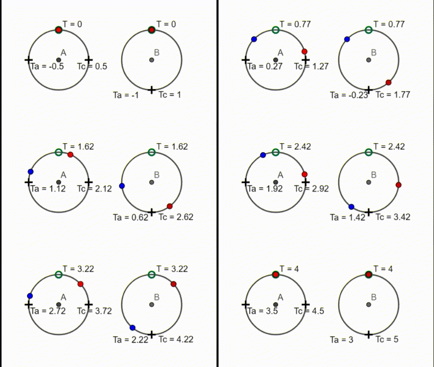
The problem is to do with conventions used for synchronising. In the linear setting, the Einstein clock synchronisation convention assumes the speed of light is isotropic. This is fine in the linear setting as there is no way to measure the the one way speed of light in the linear case. In the circular case, the speed of light is not isotropic in the rotating reference frame. A signal going all the way round clockwise takes longer to return to the start than a signal going anti-clockwise, if the disc is rotating clockwise. You can however use Einstein synchronisation in the circular setting and then get $\gamma(t_1-t_2) = 0 $ as you would expect. The only problem is that you need one sets of clocks with an advanced offset around the perimeter to measure clockwise signals and another set of clocks with retarded offsets to measure anticlockwise signals. We end up with the strange situation of clocks that are adjacent to each other with different offsets. This situation arises from trying to maintain the illusion that the light is isotropic in a rotating reference frame, when it is not.
enter image description here

In the above animation, the clocks are synchronised exactly as per the Einstein convention, by setting the clocks at the mirrors to half the round trip time. The disc is rotating anticlockwise, so its takes longer for anticlockwise signal to reach the mirror, so the anticlockwise clocks (Ta) have a negative offset and the clockwise clocks have a positive offset (Tc). This means Ta=Tc or equivalently, $\gamma(t_1-t_2) = 0 $. Everything is as per the linear case, but when the signals cross each other, the different offsets become obvious. You can imagine cutting the ring in half at the lower section and bending the circle into a straight line. You would end up with the linear case. An alternative method of synchronising the clocks is what I call the lighthouse method. All the clocks are set to zero simultaneously by a signal from the centre. It would become obvious then the light signals are not isotropic in the rotating reference frame. This is not too radical a concept. In the Schwarzschild metric, the speed of light is not isotropic either to a stationary observer in the gravitational field, except very locally.

(Just in case it not clear, the two clocks at the lower part of the right hand animation are at the same location.) The signals arrive 'simultaneously' at that location, if you read the right clock, but of course it is obvious that they do not really arrive simultaneously, which is a consequence of the reality, that the speed of light is direction dependent in a rotating reference frame.
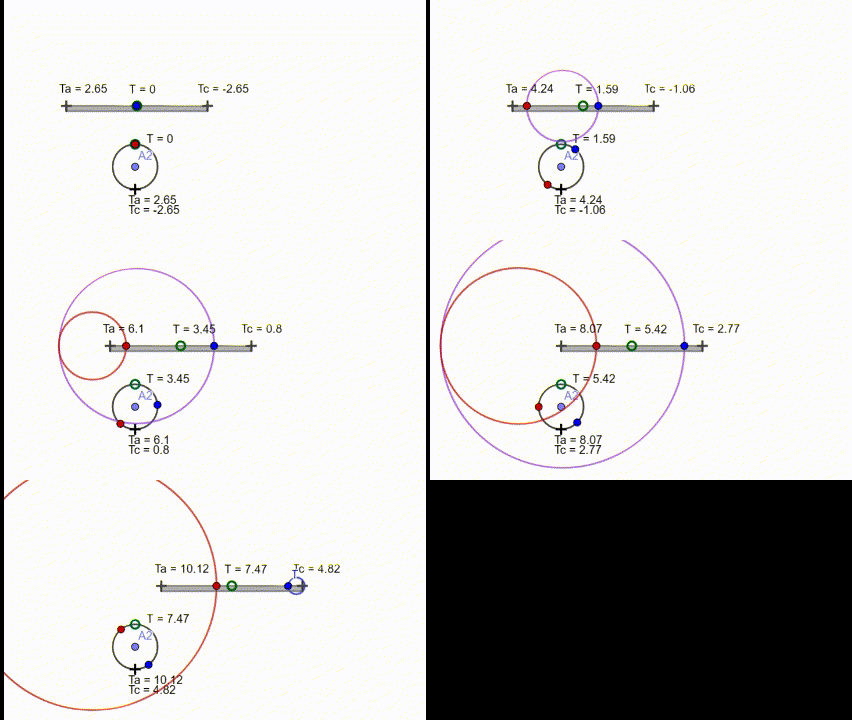
enter image description here

The above animation more directly demonstrates the equivalence of the linear and Sagnac forms. Note that despite the one way speed of light being c in both directions in the linear case and effectively 3/4 c clockwise and 2 c anti-clockwise in the rotating case, the measured times are identical. This demonstrates the complete insensitivity off Einstein synchronisation to the one way speed of light.

How would one actually compute t1 and t2 in the comoving frame in the circular setting? – Hans

As shown above if Einstein synchronisation is used in the circular setting, the calculations and results are exactly the same as in the linear case. If the rotating clocks are synchronised by a central signal then what appears to be simultaneous to the co-rotating obverses also appear s synchronised to a none rotating observer that is stationary relative to the centre the rotating frame.

Using this method,

$t_1 = \frac{L_0}{c\gamma (1-\beta)}$
$t_2 = \frac{L_0}{c\gamma (1+\beta)}$

where $L_0$ = the proper length of the rod or the proper distance along the perimeter.

$$t'_1-t'_2 = \left[\frac{L_0}{c\gamma (1-\beta)}\right] -\left[ \frac{L_0}{c\gamma (1+\beta)}\right] = 2L_O \frac{\beta \gamma}{c}= (t_1+t_2) \beta \gamma $$

where $L_0 = c(t1+t_2)/2$ (The there and back time is halved)

You made a small error or omission in your addition calculation where you got $t_1'+t_2'=2\gamma\ $ which should be $$t_1'+t_2'=2L_0\frac{\gamma}{c}=2L_0\frac{\gamma}{c}$$

which is now dimensionally correct.

$\endgroup$
6
  • $\begingroup$ I get what you are saying. You give a plausible reason why the linear setting could be different from the circular one when a mirror is set at 1/4 and 1/2 position. What about the case when the photon continues on until returns back to the starting point in the circular setting? How would one actually compute $t_1$ and $t_2$ in the comoving frame in the circular setting? $\endgroup$
    – Hans
    Commented May 28 at 5:05
  • $\begingroup$ @Hans If you have clocks at regular intervals all the way around the perimeter, you will need to clocks at every location, using Einstein synchronisation. On set of clocks is used for clockwise measurements and the other set of clocks for making anticlockwise measurements. This is not ideal and artificial. A better synchronisation method would be to use a synchronising signal at the centre. Noe rotating and co-rotating observers would agree on simultaneity, but the rotating clocks would tick slower than the none rotating ones. $\endgroup$
    – KDP
    Commented May 28 at 5:29
  • $\begingroup$ If you stay with Einstein synchronisation and the doubled up clocks, the calculations are exactly the same as in the linear case. I could do he calculation for a centralised synchronisation which only requires one set of clocks, but that probably deserves its own question. $\endgroup$
    – KDP
    Commented May 28 at 5:32
  • $\begingroup$ If you use Einstein synchronisation to measure the time for a signal to go twice around the loop, you would need 4 clocks at each location. Einstein synchronisation is obviously not ideal in the circular setting. $\endgroup$
    – KDP
    Commented May 28 at 5:37
  • $\begingroup$ @Hans I have added yet another animation to my answer. I hope you find it useful and enlightening. $\endgroup$
    – KDP
    Commented May 29 at 22:03
-1
$\begingroup$

As for $t_1-t_2$, the difference between the linear and circular cases is that in the linear case, you can arrange for two unprimed clocks that are a distance $2πr$ apart in the lab (primed) frame to be desynchronized by $2πrβ$ relative to the lab-frame clocks, as required by the Einstein convention. In the circular case you can't, because they're the same clock, and can only have one time offset from the lab clock.

As for $t_1'-t_2'$, technically there should be a factor like $γ$ in the circular case too, but it can be ignored because it's quadratic in $β$ while the Sagnac effect is linear in $β$. I say like $γ$, not equal to it, because there is no principle of relativity of angular velocities, so the effect of rotation on the apparatus can and will be much more complicated than the simple kinematic $γ$ factor.

$\endgroup$
3
  • $\begingroup$ But why in the circular case, the same clock has to register two distinct elapsed times for the two opposite trips? Can you give the detailed derivation? $\endgroup$
    – Hans
    Commented May 22 at 22:05
  • $\begingroup$ @Hans In the circular case, it's an objective fact that light pulses emitted in opposite directions at the same time arrive back at different times, no matter what clocks you use. The arrival events are timelike separated. In the linear case, they're spacelike separated and there are inertial frames in which they happen at the same coordinate time. The derivation is just a matter of tracing the worldlines of the light beams (which are helical in the circular case). You can do it in any inertial frame since they're all equivalent, but it's easiest in the rest frame of the center of the circle. $\endgroup$
    – benrg
    Commented May 22 at 23:43
  • $\begingroup$ This is too hand-wavy a response. Would appreciate if you would deign to write out the full derivation in your answer. $\endgroup$
    – Hans
    Commented May 23 at 20:15

Your Answer

By clicking “Post Your Answer”, you agree to our terms of service and acknowledge you have read our privacy policy.

Not the answer you're looking for? Browse other questions tagged or ask your own question.