5
$\begingroup$

I have a very specific question concerning a system with a magnet and a wire.

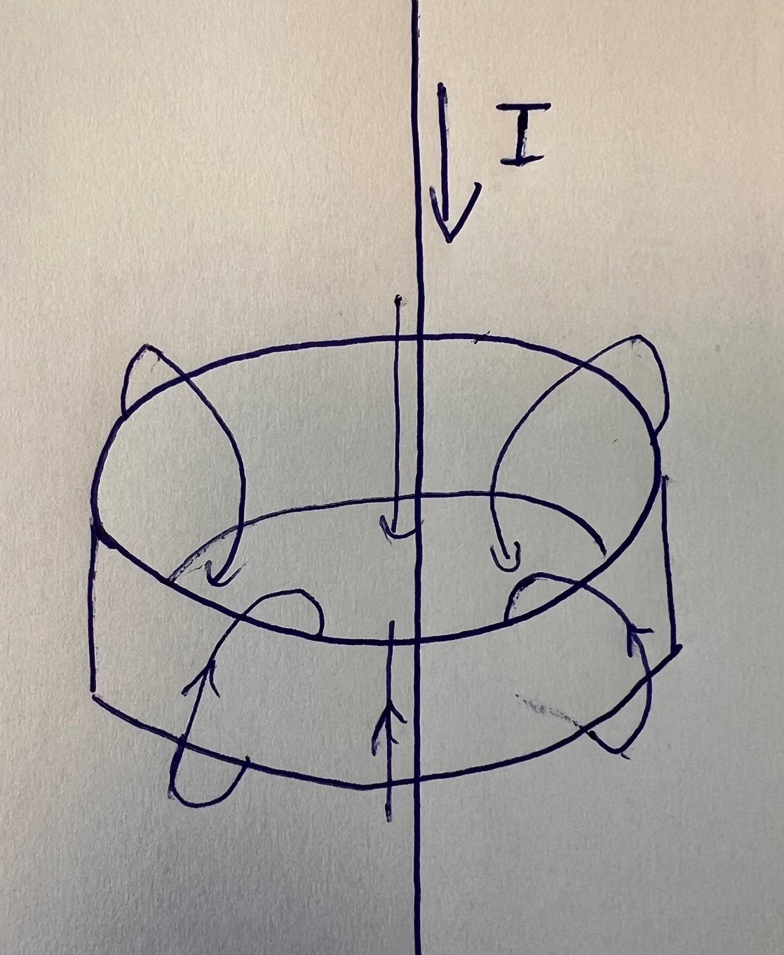
Consider a ring magnet with a magnetic field directed right through its center. In the center of the magnet is a wire, through which a current $I$ is flowing. This also creates a magnetic field around the wire.

Correct me if I am wrong but I think the resulting force on the wire should push it right into the middle of the magnet.

The remaining question that I have is how do I calculate resulting force in this contraption, which is dependent on the magnetic field $B$ of the magnet on its inside and the current flowing through the wire?

I have put a sketch right below for you to understand it better.

enter image description here

$\endgroup$
9
  • $\begingroup$ A tip to calculate this: Your problem is radially symmetric, so it suffices to consider the radial displacement of the wire. $\endgroup$
    – paulina
    Commented Apr 30 at 8:29
  • $\begingroup$ This is a complex 3D problem as the field due to magnet is non-uniform otherwise there is no interaction between the wire and the magnet. I would suggest that instead of the ring magnet you have a loop of wire carrying a current $i$ producing a magnetic field. If the wire is perpendicular to the plane of the coil and not at the centre of the loop, it appears that a couple is exerted on the wire trying to move it away from the vertical. $\endgroup$
    – Farcher
    Commented Apr 30 at 8:51
  • $\begingroup$ Actually, both of our answers assume that your ring like magnet is akin to a single solenoid by interpreting the looped arrows encircling it as magnetic field lines. However, it is not possible to generate such fields just by magnetising the ring . What is the orientation of the magnetisation of the ring? Perhaps you were graphing surface currents with the magnetisation along the orthoradial direction? $\endgroup$
    – LPZ
    Commented May 3 at 10:15
  • $\begingroup$ @LPZ I would assume the ring to have the magentic field of Fig.2 of the answers from Markoul11 $\endgroup$
    – Mo711
    Commented May 3 at 13:54
  • $\begingroup$ That's what I suspected. As I've mentioned in the previous comment, it's not possible to generate such a field using a ring shaped permanent magnet. It's only possible with an electromagnet, the solenoid that both Markoul11 and I considered. $\endgroup$
    – LPZ
    Commented May 3 at 14:15

3 Answers 3

2
+50
$\begingroup$

In magnetostatics, permanent magnets and electromagnets have the same effect, so for the computations, I'll assimilate the ring magnet as a solenoid. There are many methods for computing the force. The short answer is that paradoxically, the magnet applies no net force on the wire. Naturally, this will not apply anymore for AC currents, and only holds for DC currents. It's still a good sanity check for the AC case, as it means that the force is proportional to the frequency hence the canceling at zero frequency.

The first natural method is to integrate the force applied by the solenoid's field on the wire: $$ F = I\int B\times ds $$ with $B$ the field generated by the solenoid and $ds$ the line element of the wire. You would therefore first need to compute the field $B$ which does not have a simple expression and then integrate it making it complicated.

Another way is to first compute the mutual inductance of the wire and the solenoid $M$. It describes the interaction magnetic energy between the two that will depend on the position of the wire. More precisely, at fixed currents, $-M$ describes the mechanical potential energy between the two currents due to the magnetic force's work. The wire, if free to move, will therefore try to maximise $M$ and a maximum in configuration would correspond to a stable mechanical equilibrium.

Computing the mutual inductance is much easier, you just need to compute the flux of the field of one of the currents across the other current. The solenoid generates a field in the $r,z$ plane, so the flux across the wire is zero as can be seen by taking a half plane that contains the solenoid's field. Equivalently, the flux of the wire's field across any current loop forming the solenoid is zero, since the field is orthoradial and you can take a surface to be the disk perpendicular to the axis.

To conclude, the mutual inductance is zero, no matter the position of the wire. By taking the derivative, the force is zero, so the equilibrium is neutral.

Note that if you allow the wire to rotate, part of the reasoning is salvageable. Mutual inductance is zero as long as the wire lies in a plane of symmetry of the solenoid. When it leaves it, you have a non zero mutual inductance. In fact, you can prove that the wire being parallel to the axis of the solenoid is an unstable equilibrium. The wire will tend to align with the direction of the current of the solenoid's loop (i.e. tilt) and is repelled from the center.

Hope this helps.

$\endgroup$
7
  • $\begingroup$ So you are saying, that the flux of the wire's field across the current loop is zero as well as the flux of the current loops field across the wire is zero, But is this mutual inductance equivalent to the field, that we can assume form other calculations? $\endgroup$
    – Mo711
    Commented May 3 at 13:49
  • $\begingroup$ I agree with the analysis of LPZ which comes to the same conclusion of the deflection of the wire with the exception that an air solenoid does not emulate accurately the field of a ring magnet since the field inside the solenoid is near-homogeneous especially for a relative long solenoid. Instead, a single loop current generated magnetic field emulates best the field of a permanent ring magnet. With that said, LPZ's analysis shows very nicely that even with an homogeneous field the result will be the same for the wire, as long as one of the the two fields in superposition is inhomogeneous. $\endgroup$
    – Markoul11
    Commented May 3 at 14:48
  • $\begingroup$ totalelement.com/blogs/about-neodymium-magnets/… This shows nicely the different magnetic fields for various magnets. The air cap field of a ring magnet has less curl than a disk magnet therefore emulates more closely the field of a single current loop. A solenoid has multiple loops that will stretch the inner field making it near homogeneous whereas a single loop has a more curled field inside the air cap matching that of a ring magnet axially magnetized. $\endgroup$
    – Markoul11
    Commented May 3 at 21:05
  • $\begingroup$ @LPZ Sorry to say, but this linked image you are referring of the field of a short length axial ring magnet is misinterpretation and wrong application of a technical formula for the flux density calculation of the field wrongly applied for the inner air cap of the magnet. This formula is indented to calculate only the field of an axial ruing magnet for a distance z from the face of the magnet and NOT its inner air center origin. Somebody, took literally this equation and simulated this graph that is utterly nonsense with magnetic polarity flip in the air cap! tinyurl.com/24mpaka7 $\endgroup$
    – Markoul11
    Commented May 4 at 9:04
  • $\begingroup$ I found also the source of this equation in supermagnete.de : tinyurl.com/4nar6wx3 . A much more accurate simulation of the field of an air cap ring magnet can be found here from K&J magnetics, tinyurl.com/bdduxmpb . The B field is stronger aat the actual ring magnet body and dims progressively inside its air cap as we approach the center. $\endgroup$
    – Markoul11
    Commented May 4 at 9:20
1
$\begingroup$

Both magnetic fields are highly inhomogeneous.

Using this online simulator here we get the following results of the generated magnetic vectors:

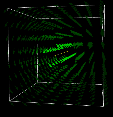
$1)$ Current line $10A$. Current is flowing out of your monitor screen perpendicular, and towards you.

Current line 10A

Fig.1 Current line Magnetic Vector Field simulation

Simulation Link: https://www.falstad.com/vector3dm/vector3dm.html?f=InverseRotational&d=vectors&sl=none&st=20&vd=16&rx=0&ry=0&rz=0&zm=1.2

Note: You can hold the simulation image and rotate it.

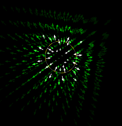
$2)$ Current loop (i.e. this is analogue for a single loop with the field of a ring magnet), North magnetic pole of field is facing you, current in the loop is moving counterclockwise.

Ring Magnet

Fig.2 Ring magnet Vector Field simulation

Simulation Link: https://www.falstad.com/vector3dm/vector3dm.html?f=CurrentLoopField&d=vectors&sl=none&st=20&vd=16&a1=40&rx=73&ry=0&rz=0&zm=1.2

Note: You can hold the simulation image and rotate it.

Assuming the ring magnet is mechanically fixed in place and cannot move and the wire line can move from the center position and using vectors superposition it is clear that the current wire cannot remain balanced at the center and will be attracted by the ring magnet's inner walls.

Furthermore, Earnshaw's theorem states that it is impossible to balance two inhomogeneous static magnetic fields.

Fun factor: Assuming you are not using a d.c. current on the wire line but an a.c. current instead of very low frequency, say 2-5 Hz then I predict the wire will rapidly move and collide with the inner walls of the ring magnet at different random positions each time resembling the rapid mechanical switching of an electric relay device.

$\endgroup$
5
  • 1
    $\begingroup$ Thanks for your answer, I am struggeling a little to understand the vectors superposition, which would result in a force pulling the rope to the inner wall. But what would happen if we used a very high ac Frequency, wouldn't that keep the wire centered? $\endgroup$
    – Mo711
    Commented May 3 at 9:10
  • $\begingroup$ "But what would happen if we used a very high ac Frequency, wouldn't that keep the wire centered?" That is a very interesting suggestion! Say for a example a 1KHz a.c. signal on the wire. Assuming the current to be of enough amplitude to compete with the field of the ring magnet theoretically this is possible I believe. The wire will continuously and very fast try to adjust keeping it at the center. But you have to experiment to make sure. $\endgroup$
    – Markoul11
    Commented May 3 at 9:17
  • $\begingroup$ @Mo711 Also, you should initially support mechanically the wire at the center for 2-3 seconds before releasing it. $\endgroup$
    – Markoul11
    Commented May 3 at 9:19
  • $\begingroup$ Answer is now updated with new information concerning Earnshaw's theorem in regard to static magnetic fields. $\endgroup$
    – Markoul11
    Commented May 3 at 9:27
  • $\begingroup$ @Mo711 A small demonstration of how a dynamic magnetic field can be used for achieving equilibrium and levitation: youtube.com/watch?v=V5FyFvgxUhE $\endgroup$
    – Markoul11
    Commented May 12 at 14:34
0
$\begingroup$

The force on a charge $q$ with velocity $\vec v$, in a magnetic field $\vec B$, is $\vec F=q\vec v\times\vec B$.

Using cylindrical coordinates, wire initially in $z$ direction at $r=0$, so the velocity of the charge is in the $z$ direction. Magnet centered at $z=r=0$, so at $r=0$, its magnetic field is only in $z$ direction, so no force on wire since the velocity is parallel to the field and the cross product is zero, $q\vec v\times\vec B=0$.

Now make an infinitesimal displacement of the wire outward in the $r$ direction at $\theta=0$. The velocity of the charge is still in the $z$ direction, but the magnetic field now gets an infinitesimal $r$ component, not a $\theta$ component, and then the cross product $q\vec v\times \vec B$ gives an infinitesimal force in the $\theta$ direction, so it seems to me, at first glance, to be neither a restoring force back to center in the $r$ direction, nor a force to pull the wire to the inside edge of the ring magnet along the $r$ direction, rather a force to deflect circularly in the $\theta$ direction.

At 2nd glance I'd add that at $z=0$ there's no force still as the $\vec B$ field only has a $z$ component. The infinitesimal $\theta$ force occurs above $z=0$, and below $z=0$ the $\theta$ force occurs in the opposite direction.

$\endgroup$
1
  • $\begingroup$ As it’s currently written, your answer is unclear. Please edit to add additional details that will help others understand how this addresses the question asked. You can find more information on how to write good answers in the help center. $\endgroup$
    – Community Bot
    Commented May 4 at 22:23

Your Answer

By clicking “Post Your Answer”, you agree to our terms of service and acknowledge you have read our privacy policy.

Not the answer you're looking for? Browse other questions tagged or ask your own question.