13
$\begingroup$

"The velocity gradient in turbulent flows is steeper close to the wall and less steep in the center of the pipe than it is for laminar flows (Blatt p.97)."

Does this mean that some degree of turbulence near the wall of a pipe may actually improve the energy efficiency of pumping a fluid? I realize that turbulence tends to increase the energy required, but perhaps just the minimum amount in the right place might prove advantageous. Have surface modifications to increase turbulence been investigated for potential efficiency?

"The eddy viscosity is generally much larger than the dynamic viscosity (Blatt p.111)." This would suggest that larger diameter pipes would be better candidates for turbulence assisted flow, since the volume to surface area ratio is larger.

Icebreakers bubble air past their hulls to lubricate the ice scraping against their hulls. Specially tailored turbulence might be able to lubricate the sliding the bulk of the fluid as virtually "extruded" past controlled turbulence. The efficiency of the turbulence would likely be velocity dependent.

Relevant Information: The Darcy-Weisbach equation is used to describe the pressure loss over a given segment of pipe.

Blatt, Middleton, and Murray, "Origin of Sedimentary Rocks," 2nd Ed.

$\endgroup$
2
  • $\begingroup$ Interesting question, what I am thinking is that turbulence is erratic by nature, it is a process where various fluid quantities show a random variation with time and space. As such, I do not see how the transport efficiency would be improved. $\endgroup$ Commented May 6, 2013 at 20:21
  • $\begingroup$ researchnews.osu.edu/archive/riblets.htm $\endgroup$
    – Dale
    Commented Jun 6, 2013 at 16:49

3 Answers 3

2
$\begingroup$

No it cannot in the general case. The formulas giving the pressure loss in a duct are always given by a form P = K.geometry.rho.V² where K is an empirical friction coefficient, geometry contains geometrical parameters (diameter, length etc), rho is the density and V the velocity.

Now K depends typically on the Reynolds number and on the roughness of the duct wall. Once the nature of the fluid and the geometry of the duct fixed, the pressure loss depends only on K.V².

What does it mean "increasing turbulence" in the duct? Only 2 possible answers :

1) Increasing the velocity. As this increases both K and V², it increases the pressure loss. Bad.

2) Increasing the roughness of the duct. This increases K without changing V. The pressure loss increases again. Bad.

Of course very low velocity laminar flows are also very bad pressure loosers but then they move so little fluid that they are not used anyway. Going from laminar to turbulent may be better or worse depending on the rougness but one has generally no choice because the flow (kg/s) is a constraint and the turbulent flow is the result. Once the turbulent flow given, best is to reduce the roughness as far as it goes.

You have an excellent calculator here and you can play with all kinds of possible flows : http://www.engineeringtoolbox.com/colebrook-equation-d_1031.html

As a bonus there is also a chart for Darcy friction coefficients depending on Reynolds and roughness.

$\endgroup$
1
$\begingroup$

Yes: up to a point

The Darcy Weisbach equation accounts for frictional losses in a pipe:

$f L D \frac{v^2}{2 g}$

$f$ typically comes from a Moody Diagram. Looking at one you'll see that the friction factor for a pipe decreases with increasing Reynolds number until the flow is deemed "fully turbulent" at which point the friction factor levels off.

The physical reason for this is a turbulent boundary layer forms at the edge of the pipe, making the pipe effectively smoother. The mean velocity profile of a low Reynolds number pipe flow is parabolic, while a high Reynolds number flow is more uniform, and so the flow "feels" the walls of the pipe less.

A pipe going from reynolds number 3,000 to 300,000 could see a reduction in it's friction factor by almost half, but a pipe going from Re 300,000 to 3,000,000 will see almost no reduction in friction factor.

$\endgroup$
0
-1
$\begingroup$

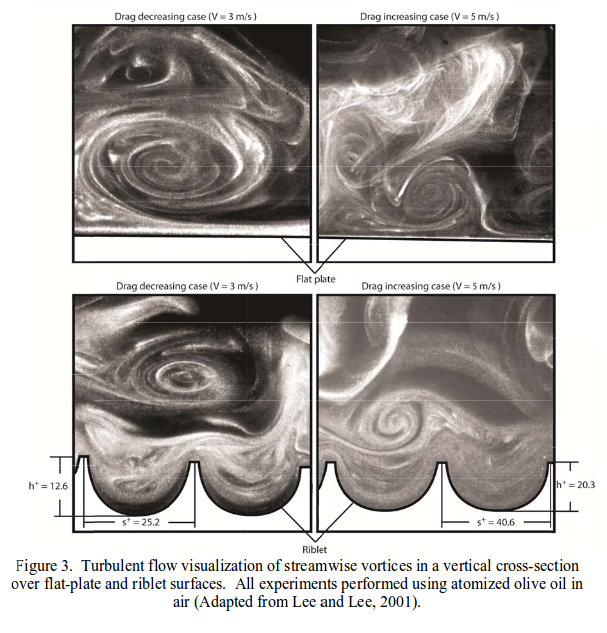
Riblets can improve fluid flow in a pipe by 3-15%. They were initially discovered while studying shark skin.

The small riblets that cover the skin of fast swimming sharks work by decreasing the total shear stress across the surface and by impeding the cross-stream translation of the streamwise vorticies in the viscous sublayer. While these effects and their role in the final reduction of drage are understood and reproducible, the underlying mechanisms which cause the reduction in vortex translation are not fully understood.

One classical cause of increased drage that shark skin-mimicking riblet surfaces exhibit is an increase in wetted surface area. In the turbulent flow regime, fluid drag typically increases dramatically with an increase in surface area due to the shear stresses at the surface acting across the new, larger surface area. However, as vorticies form above the riblet surface, they remain above the riblets, interacting with the tips only and rarely causing any high-velocity flow in the valleys of the riblets. Since the higher velocity vorticies interact only with a small surface area at the riblet tips, only this localized area experineces high shear stresses. The low velocity fluid flow in the valleys of the riblets produces very low shear stresses across the majority of the surface of the riblet. By keeping the vorticies above the riblet tips, the cross-stream velocity fluctuations inside the riblet valleys are much lower than the cross-stream velocity fluctuations above a flat plate (Lee and Lee, 2001). This difference in cross-stream velocity fluctuations is evidence of a reduction in shear stress and momentum transfer near the surface, which minimizes the effect of the increased surface area. Source: "The Effect of Shark Skin Inspired Riblet Geometries on Drag in Rectangular Duct Flow." Brian Doublas Dean, Ohio State University, 2011.

The effectiveness of riblets is very much dependent on the fluid's velocity.

enter image description here

There is a large literature about drag reduction using riblets in turbulent boundary layer flow over flat plates. Some of the earliest and more important results were obtained by Walshs$^{1,2,3}$. He showed that drag reduction could be obtained when the height of the riblet structure expressed in wll units $S^+ =\frac{Su^+}{v}$ is below 30; the maximum of 7-8% occurred when $S^+$ is about 15. Here S is the height and base of the riblets, $u^+$ is the friction velocity and $v$ is the kinematic visciosity. He also found that triangular grooves are among the most effective in reducing drag.

Less is known about the effect of riblets on drag reduction in pipe flow. Nitschke$^4$ studied air flow in a pipe with rounded peaks and flat valleys machined into the pipe surface. A maximum drag reduction of 3% was measured.... At larger speeds riblet linings lead to drag increase. Source: "Drag Reduction in Pipes Lined with Riblets." K.N. Liu, C. Christodoulou, O. Ciccius, C.C. Joseph, University of Minnesota, Minneapolis, MN.

Turbulence may also be reduced to increase efficiency through applying a Superhydrophobic coating.

$\endgroup$
0

Your Answer

By clicking “Post Your Answer”, you agree to our terms of service and acknowledge you have read our privacy policy.

Not the answer you're looking for? Browse other questions tagged or ask your own question.