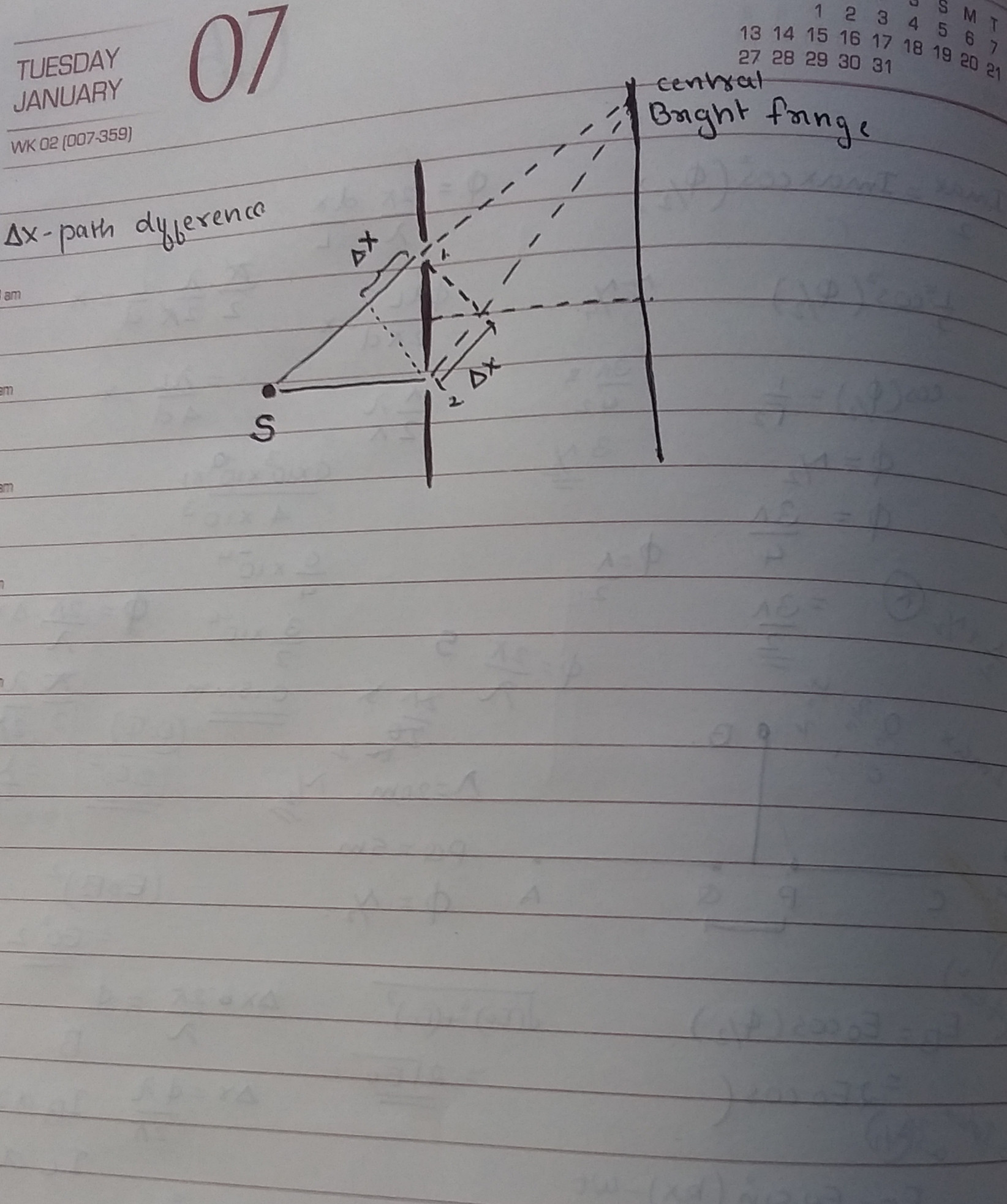
I believe here is a misconception from the figure above.
The source is not actually placed where the dot is in your picture, I believe it is there merely to illustrate further the path difference experienced on the other side of the slit. The slit experiment shows that on the other side of this slit we get an interference-pattern as if the incident information was that of a wave. The slits acts as point sources of waves. The incident wave/particles on the other side does not have to be from a source that you've marked out on your paper. The input could be one plane wave approaching the interface, on the other side we'd have the same interference-pattern as if we have had two circular waves approaching from different angles upon the slits. The slits acts as point sources and thus the interference pattern is the same. What affects the pattern on the other side however would be wavelength on the incident wave or separation of slits etc as this would affect the relative path difference of the two components.
Observe the lower ray you've drawn, if we look at the angles as absolute and analyse the problem with a ray approximation, why does the lower one bend in that way? This is simply a simplification of a wave, where the rays drawn are that of wave components which would interfere on that point on the rightmost screen.

