7
$\begingroup$

I was watching a video of Walter Lewin (8.02x-Lecture 16 to be precise), where he demonstrates an experiment which violates the Kirchhoff's Law.

The way I interpret Kirchhoff's laws is by imagining the battery as being a waterfall, and all the electric components being placed along the flow, harvesting the flow. Therefore it's commonsensical to say that the potential difference across the components equals that of the entire waterfall.

At first sight, his experiment seemed flawed to me since how can the potential difference vary along a negligibly resisting wire, for two resistors? But after further insight and some discussions with my educator, I was led to the conclusion that the discrepancy here was being caused by the connecting wires, which had some potential difference across them as well, therefore Kirchhoff's laws hold!

To quote my educator:

A varying magnetic field leads to the conception of circumferential electric fields in the plane perpendicular to the magnetic field. It is these electric fields which serve as an EMF source(since they move the electrons in the conductor), and hence there is a potential difference across the conductors proportional to the length.

For me, the above explanation was correct since it was in-line with everything I'd studied so far, and I discarded Walter Lewin's argument considering it to be a small mistake from his end(which is weird since he always corrects himself sooner or later).

Here are some of the illustrations which my educator had used while explaining it to me.
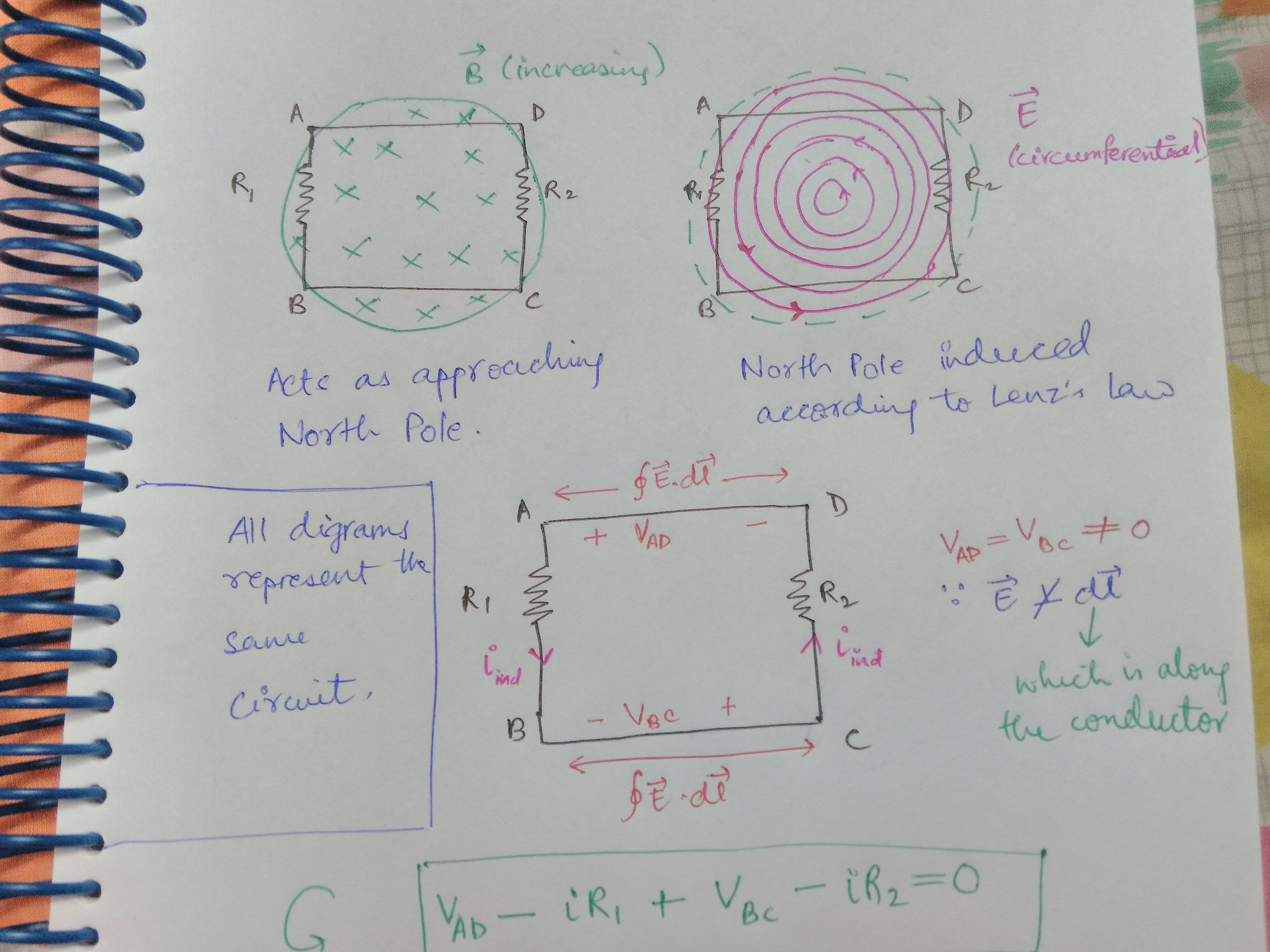
The problem, or maybe an opportunity to correct myself, arose today when I saw that Walter Lewin confirmed that what he had demonstrated was true.

So my question here is what should I, as a class 12th student, believe to be true? I'm really curious about this whole phenomenon and want to understand it. Also, is the argument involving the circumferential electric fields correct? Are Kirchhoff's laws really violated?

$\endgroup$
8
  • 2
    $\begingroup$ In fact, when there is changing B field, the usual electrical potential cannot be defined. $\endgroup$
    – K_inverse
    Commented Nov 8, 2018 at 11:55
  • 1
    $\begingroup$ You're aware that Kirchhoff's circuit laws are approximations that hold exactly only in the non-time varying, lumped element limit? See Kirchhoff's circuit laws:Limitations $\endgroup$ Commented Nov 8, 2018 at 12:40
  • 1
    $\begingroup$ @K_inverse Actually it can still be defined, and it is related to electric field by $\mathbf E=-\partial_t \mathbf A- \mathbf\nabla \phi$ where $\mathbf A$ is the vector potential $\endgroup$
    – Nicolas
    Commented Nov 8, 2018 at 13:14
  • $\begingroup$ @Nicolas Absolutely, but $\phi$ here is not the same as the electrical potential that we used to in magnetostatic case. $\endgroup$
    – K_inverse
    Commented Nov 8, 2018 at 15:26
  • 1
    $\begingroup$ It'd be interesting to see answers addressing the recent videos by ElectroBOOM and a follow-up by Lewin $\endgroup$ Commented Nov 11, 2018 at 16:30

2 Answers 2

7
$\begingroup$

It depends on exactly what formulation you want to use for Kirchhoff's laws in non-static situations where you have time-dependent magnetic fields permeating your circuit. However, if you understand the Kirchhoff voltage law as stating that the current-times-resistance of all the elements in a closed loop must equal zero, then yes, that statement can be violated in real-world scenarios.

The water-flowing-down-a-channel mental model for electric fields is extremely useful in electrostatic situations, where its validity follows from the statement that the electrostatic field is conservative, i.e. $$ \oint_C \mathbf E(\mathbf r)\cdot \mathrm d\mathbf l = 0 \tag{$*$} $$ (so therefore it is appropriate to model that force with other conservative forces, like the gravity that powers the water-in-a-channel in that analogy).

However, when your situation is no longer electrostatic and there is a changing magnetic flux permeating your circuit, the electric field is no longer a conservative vector field, and the relation $(*)$ needs to be replaced with the Faraday-Henry induction law, $$ \oint_C \mathbf E(\mathbf r)\cdot \mathrm d\mathbf l = -\frac{\mathrm d}{\mathrm dt} \iint_S \mathbf B(\mathbf r) \cdot \mathrm d \mathbf S . \tag{$**$} $$ The statement that there is a changing magnetic flux permeating your circuit is equivalent to saying that the right-hand side of that equation is nonzero, and the usual electrostatic understanding of the Kirchhoff voltage law is no longer valid.

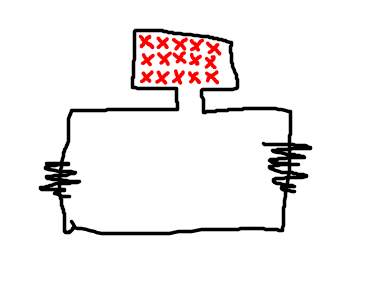
Now, there are indeed some ways to reconcile these statements with the usual understanding which allow us to apply that intuition to a broader set of regimes. This includes, for instance, regarding the right-hand side of $(**)$ as an EMF acting on the whole circuit and then split it up as usual among the resistances in the circuit. This is particularly the case if the flux region is confined to a small section of the loop, say, something like this,

enter image description here

and you're not going to fiddle with the internals of that loop. (This is e.g. exactly what happens if you have an AC circuit driven by a transformer.) In such a situation, you can use the Kirchhoff voltage law as usual and treat the smaller sub-loop as a single EMF, and everything will work fine; if you connect voltmeters on the terminals of your resistors, you'll see the voltage law work just fine. But, of course, if you connect them to parts of the inner loop (which is isomorphic to what Lewin has done) then you'll see the same deviations.

$\endgroup$
2
  • $\begingroup$ I read your answer, and I think it's similar to what I had proposed above, so correct me if I'm wrong. In my question, I've stated(or rather what my educator said) that it is due to the connecting wires, bearing a potential difference across them, that the KVL seems to fail at first sight, which isn't true since we haven't applied it properly. What I'd like to ask is, is the image illustration correct, especially the $V_{AD}-iR_1+V_{BC}-iR_2=0$ part? $\endgroup$ Commented Nov 9, 2018 at 5:24
  • 1
    $\begingroup$ You haven't defined those symbols precisely enough for that question to have an answer. $\endgroup$ Commented Nov 9, 2018 at 7:54
3
$\begingroup$

The key to reconcile this discrepance in the lumped-element abstraction is to consider the inductance of the loop as an additional circuit element. Kirchhoff's voltage law derives from Faraday's law that states that in a closed loop: $$ \oint_R {\vec E \cdot d\vec R} = - \int_S {\frac{{\partial \vec B}}{{\partial t}} \cdot d\vec S} $$ Where $S$ is an open surface whose boundary is the closed loop $R$. The line integral can be decomposed in different path integrals, each one traversing a specific cicuit element: $$ \int_A^B {\vec E \cdot d\vec R} + \int_B^C {\vec E \cdot d\vec R} + \int_C^D {\vec E \cdot d\vec R} + \int_D^A {\vec E \cdot d\vec R}= - \int_S {\frac{{\partial \vec B}}{{\partial t}} \cdot d\vec S} $$ Each path integral is the voltage of its associated circuit element (which can be time-varying without problem, we already specified a path by defining the loop $R$). Therefore: $$ v_{AB} + v_{BC} + v_{CD} + v_{DA} = - \int_S {\frac{{\partial \vec B}}{{\partial t}} \cdot d\vec S} $$ Now, the emf on the right side can be expressed in terms of the loop inductance: $$ \int_S {\frac{{\partial \vec B}}{{\partial t}} \cdot d\vec S} = L \frac{di_L}{dt} = v_L $$ Where $i_L$ is the loop current, notice that this emf has units of voltage, so we can think of it as the voltage of a specific lumped element called inductor, which is specific of each loop (and notice that the inductor's voltage drops to zero in DC, because $i_L$ becomes constant). We can consider this inductor as an additional element of the loop, so we move this voltage to the left side and we have: $$ v_{AB} + v_{BC} + v_{CD} + v_{DA} + v_L= 0 $$ In general we have for any loop: $$ \sum_{k=1}^{n}{v_k} = 0 $$ Which is the Kirchhoff's voltage law.

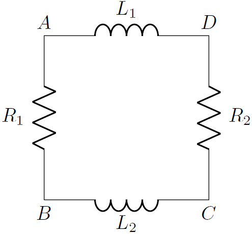
To sum it up, the abstraction you are using to model the experiment as a circuit is failing because you are not being detailed enough, you must include the loop inductance, which would give you a loop like this one:

fig1

PD: I answered a similar question here, but I cannot comment so I ended up fleshing out a proper answer.

$\endgroup$

Your Answer

By clicking “Post Your Answer”, you agree to our terms of service and acknowledge you have read our privacy policy.

Not the answer you're looking for? Browse other questions tagged or ask your own question.