1
$\begingroup$

So I got 2 converging Fresnel lenses, one with 50 mm focal length and other 70 mm.

My experiment looks like this: lenses.png
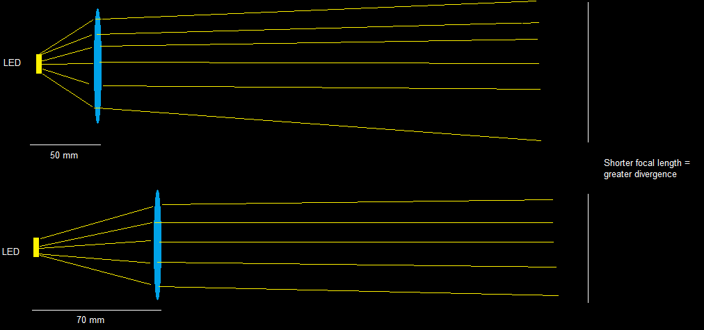
When trying to focus and SMD LED emitter into a narrow beam (sticking to lenses focal length accordingly), the one with shorter focal length gives bigger divergence (measuring spot on the wall).

I assume this has something to do with smaller angle of incidence, but running the simulation with "ideal" lens shows no difference in divergence between two cases with different angle of incidence. (On the figure 2, distance between A and b is equal)

Also, I am not sure whether they are aspherical (does it apply to fresnels?) and if no maybe this is the issue?

Untitled.png

$\endgroup$
5
  • $\begingroup$ Did you focus the image from both the lenses at the same distance form the emitter ? And is it a converging or diverging lens, asking as it is not clear from your diagram. $\endgroup$ Commented Aug 7, 2018 at 18:01
  • $\begingroup$ If you want a low divergence beam, you must use two lenses, and construct a telescope (beam expander), e.g., edmundoptics.com/resources/application-notes/optics/… $\endgroup$ Commented Aug 7, 2018 at 20:20
  • $\begingroup$ @TausifHossain Sorry for not mentioning, I focused the emitter at the both lens's focal points - where the projection were smallest. Also, the lenses are converging $\endgroup$ Commented Aug 7, 2018 at 20:55
  • $\begingroup$ @PeterDiehr Thanks for your suggestion, however this is likely not my case - beam expander requires collimated light source as an input, however I have light scattered from an LED chip $\endgroup$ Commented Aug 7, 2018 at 20:57
  • 1
    $\begingroup$ The divergence of your output beam is related to the size of your LED and the focal length of the lens. Look at a ray from an extremity of your LED through the centre of your lens. Compare this ray for both focal lengths and you'll see why the divergence is greater for the shorter focal length lens. $\endgroup$
    – D Duck
    Commented Aug 8, 2018 at 1:18

2 Answers 2

4
$\begingroup$

When the LED is placed $50mm$ from the lens, its etendue (the product of its size and the solid angle into which the LED radiates light, subtended by the lens) is greater than the etendue of the same LED placed $70mm$ from the lens of, presumably, the same size.

Therefore, due to the conservation of etendue, the divergence (solid angle) of the beam after the lens will be greater in the first scenario, i.e., for the $50mm$ lens.

$\endgroup$
2
  • $\begingroup$ Thanks for your explanation, I still need to get better understanding of etendue though=) So does this mean aspheric lens could fix this? $\endgroup$ Commented Aug 8, 2018 at 20:06
  • $\begingroup$ @eyeballpaul In order to get parallel rays (no divergence), you would need an ideal point source. Since an LED has a finite size, some divergence is inevitable and, for a given LED, it will increase as the solid angle increases (or the distance from LED to a lens decreases). A smaller LED should also reduce the divergence. You can ask a separate question regarding your best options, but you'll probably need to give more details about your application and requirements. $\endgroup$
    – V.F.
    Commented Aug 8, 2018 at 20:43
1
$\begingroup$

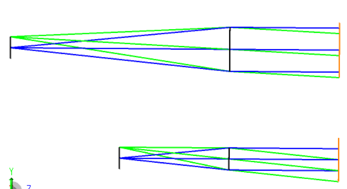
D. Duck has the best explanation - Here is a picture of what he (or she) is describing (I hope the picture shows up, pictures are helpful). This is for the case of f=50 and f=100, so that the difference in field angle is more apparent. This is what D. Duck is getting at by speaking of divergence - the field angle is set by the ray from the top of the object and goes through the center of the collimating lens. This field angle is higher for the shorter focal length lens. The ray from the top of the object through the center of the stop (in this case the collimating lens) is called the chief ray. The higher field angle will result in a larger spot after you go any appreciable distance (like across the room).

Although this problem is related to etendue, using etendue to explain this can be unecessarily confusing. In particular, the etendue argument presumes the lenses are the same size, and that may not be the case. It is simpler to show the path of the chief ray. Here is one useful formula: chief_ray_angle = atan( LED_diameter / 2 / focal_length)

enter image description here

$\endgroup$
1
  • $\begingroup$ Thanks for your great explanation, can I ask what software you were using to simulate these@ $\endgroup$ Commented Aug 9, 2018 at 18:57

Your Answer

By clicking “Post Your Answer”, you agree to our terms of service and acknowledge you have read our privacy policy.

Not the answer you're looking for? Browse other questions tagged or ask your own question.