0
$\begingroup$

In the basis $\begin{pmatrix} H \\ V \end{pmatrix}$, let us take the beam splitter matrix to be

$\begin{pmatrix} 1 & i \\ i & 1 \end{pmatrix}$

This transforms $\begin{pmatrix} 1 \\ 0 \end{pmatrix} \rightarrow \frac{1}{\sqrt{2}}\begin{pmatrix} 1 \\ i \end{pmatrix}$ and $\begin{pmatrix} 0 \\ 1 \end{pmatrix} \rightarrow \frac{1}{\sqrt{2}}\begin{pmatrix} i \\ 1 \end{pmatrix}$.

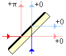
However, real beam splitters e.g. the one shown below (taken from Wikipedia) do not give the same phase shift to the horizontal and vertical inputs.

enter image description here

So is the representation there incorrect (or represents a different physical system) in which case, how do I represent the beam splitter given in the image? I'm guessing we want something that does $\begin{pmatrix} 1 \\ 0 \end{pmatrix} \rightarrow \frac{1}{\sqrt{2}}\begin{pmatrix} 1 \\ i \end{pmatrix}$ and $\begin{pmatrix} 0 \\ 1 \end{pmatrix} \rightarrow \frac{1}{\sqrt{2}}\begin{pmatrix} 1 \\ 1 \end{pmatrix}$.

But candidates like $\begin{pmatrix} 1 & i \\ 1 & 1 \end{pmatrix}$ are not unitary and this seems to be an issue.

$\endgroup$

2 Answers 2

1
$\begingroup$

The transformation matrix given by the figure would be $$ U = \frac{1}{\sqrt{2}} \begin{pmatrix} 1 & -1 \\ 1 & 1 \end{pmatrix} . $$

An alternative way to represent a beam splitter that is sometimes also used is to say $$ a \rightarrow \frac{1}{\sqrt{2}} (a+b) $$ $$ b \rightarrow \frac{1}{\sqrt{2}} (a-b) $$

In other words, the transformation is represented by a matrix $$ U = \frac{1}{\sqrt{2}} \begin{pmatrix} 1 & 1 \\ 1 & -1 \end{pmatrix} . $$ It is still unitary in the sense that $U^{\dagger}U=UU^{\dagger}=I$, but det$(U)=-1$.

The difference between these definitions and the one with the $i$'s is simply some global phase changes at the output ports, which does not give an observable effect.

$\endgroup$
0
$\begingroup$

The basic matrix $\begin{pmatrix} 1 & i \\ i & 1 \end{pmatrix}$ describes the beamsplitter if we take the "ports" of the device to be immediately next to the splitting mirror. So now we must simply compose this transformation with those that stand for the shift in reference point through the layers.

On the input side, one input travels through the glass plate, the other doesn't. The transformation wrought by the uneven pathlengths is thus $\mathrm{diag}(e^{i\,\phi},\,1)$. On the output side, the air / glass paths are swapped, so the outputs are transformed by $\mathrm{diag}(1,\,e^{i\,\phi})$. So we simply compose the three unitary matrices:

$$\begin{pmatrix} e^{i\,\phi} & 0 \\ 0 & 1 \end{pmatrix} \,\begin{pmatrix} 1 & i \\ i & 1 \end{pmatrix} \,\begin{pmatrix} 1 & 0 \\ 0 & e^{i\,\phi} \end{pmatrix}$$

More often, it is customary to remove common phases through each transformation so that the unitary matrices concerned belong to $\mathrm{SU}(2)$ (have unit determinant), but this is simply a convention that sometimes makes calculations easier. So we'd after- and fore- multiply the basic matrix by $\mathrm{diag}(e^{+i\,\frac{\phi}{2}},\,e^{-i\,\frac{\phi}{2}})$ and $\mathrm{diag}(e^{-i\,\frac{\phi}{2}},\,e^{+i\,\frac{\phi}{2}})$, respectively.

$\endgroup$

Your Answer

By clicking “Post Your Answer”, you agree to our terms of service and acknowledge you have read our privacy policy.

Not the answer you're looking for? Browse other questions tagged or ask your own question.