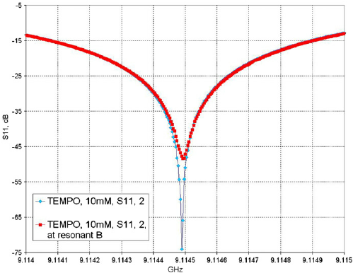
I built a resonator designed to resonate in the 10MHz-1GHz range. To verify the resonant frequency I use a network analyzer with capacitor in series with the cavity to approximate the expected load.
The physicists at my work claim that the signal should measure -20dB or less. Why is this?
My thought process:
\begin{align} \text{Gain}_\text{dB} &= 20 \log \left(\frac{V_\text{out}}{V_\text{in}} \right) = -20 \\ \rightarrow \log \left(\frac{V_\text{in}}{V_\text{out}} \right) &= 1 \\ V_\text{in} &=10*V_\text{out} \end{align} so the attenuated output signal indicates the standing wave in the resonator? Or is the -20dB a general rule of thumb?
Network Analyzer screenshot (Note: This is not my data! This is just an example to assist in clarifying my question)

